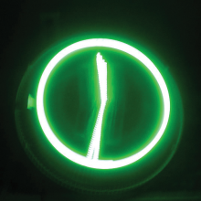
The purpose of this project was to design and build a floating LED-based clock and message display using a single row of rotating LEDs. The design consists of a row of 32 RGB LEDs controlled by a microcontroller that is rotated at a speed of around 100 rotations per second. If the LEDs are turned on and off at the appropriate time during each rotation, the eye can “connect the dots” together to form patterns that normally require large two-dimensional arrays of LEDs to display. The patterns can include graphics and text, and can also be animated.
For my project, I chose the New Year theme. The goal was to make the design perform the following sequence of tasks:
1. Start with an analog clock display consisting of the seconds, minutes and hour hands. The initial time should be 11:59:00. When the seconds hand completes one rotation, the minute hand should move to the 12:00 position.
2. At this point, the device should display an animated “ball” dropping down to ring in the new year.
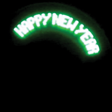
3. The device then should display the text “Happy New Year.”
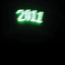
4. Finally, the device should display a flashing sign “2011.”
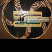
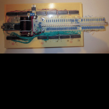
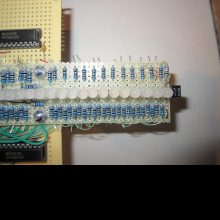
The design consists of two circuit boards, one a narrow strip for mounting the 32 LEDS in a row, and the other a 4.5x8” main board for all the circuit components. I chose the Arduino Nano 3.0 microcontroller for this project. It takes only a small area on the board and is fast enough to control the 32 LEDs at the required speed. The board has only a small number of outputs, so I used a chain of 8-bit shift registers to drive the LEDs. I constructed three chains of four shift registers each, one for each color. The 32 LEDs can be set to any combination of colors in 32 cycles by shifting data into each chain. This took only three output pins of the Nano to drive the shift register data inputs, another output to clock the data in, and three more outputs to load the outputs of the shift registers after the data has been shifted in (a total of 7 output pins).
I mounted the boards on a floor-standing fan to rotate it. I determined that the fan rotated at about 120 rotations per second in its medium speed setting, which was adequate to create the display patterns. The Arduino could set up the 32 LEDs in less than 100 microseconds, which was adequate for the project. I used the QRD1114 reflective sensor, mounted at the tip of the LED board, to determine the position of the LED arm. I mounted a white piece of paper on the fan cover at the 9 O’clock position to activate the sensor. I used a 9V battery mounted on the board to power the design.

