
Note that the Arlo Robot System is discontinued.
The Arlo Robot is a very versatile mobile robotic system. Arlo is robust, easily expandable, and provides a solid platform for autonomous robotic research and development applications. The platform is rated for up to 35 pounds of payload (that’s in addition to the Arlo Robot's own weight).
This Assembly Guide will lead you step-by-step through the entire Arlo build process. From the drive motor/encoder systems, to the assembly of the Arlo Power Distribution Board, through the wiring and electrical connections, and finally to the installation and sample programming of the Propeller Activity Board WX (#32912) - which acts as Arlo’s primary controller.
Going through the build process will provide you with a clear understanding of not only how the Arlo system physically goes together, but also how the independent components connect and interact with the sample code that we’ll provide. From then on – it’s up to you!
Although the Arlo Complete Robot System may seem to go together in a straight-forward manner, it is best to follow the assembly sequence (outlined in this guide) which may prevent you from having to do some back-up work.
This guide consists of 8 discrete physical assembly sections, starting with the Motor-Mount and Wheel Kit and ending with the installation of the control board. You will also be directed to follow a separate guide outlining electrical connections and test code for the control board you will be using (Activity Board WX - included, or BASIC Stamp Board of Education/Board of Education Shield + Arduino - not inlcuded). From that point on, you’re free to expand Arlo’s capability to wherever you want it to go.
Should the need arise, Parallax provides free tech support - either through our Forums (forums.parallax.com [1]), by email (support@parallax.com), or you can call our tech support department directly at (888)-512-1024. For missing parts, or other questions relating to your sales order, contact our sales department: 888-512-1024 within USA / 916-624-8333 outside of US, or email to sales@parallax.com.
The mechanical build process is divided into 8 sections:
Before you start the mechanical assembly process for your Arlo robot, read through this pre-build section. Let's make sure you are fully prepared and not missing any components from your kit. In case of missing parts, please contact our sales department: 888-512-1024 within USA / 916-624-8333 outside of US, or email to sales@parallax.com.

Caution! The Arlo Robot system utilizes precision-machined components that are designed to go together in a very orderly and precise manner – resist the temptation to jump-ahead. Going slow and steady will produce a reliable and expandable platform that can act as a test-bed for some amazing robotic applications.
Warning! Be very careful when you reach the point where you’re connecting the power source (batteries) to the Arlo System – correct polarity is VERY important! The 12V Sealed Lead Acid batteries (the ones that we recommend, and that are included in the Arlo Complete Robot System) have a very high discharge current capability. Connecting them prematurely or incorrectly can result in damaged components, "magic smoke" release, or overheating of the batteries themselves. With great capacity, comes great responsibility!
The Arlo Complete Robot System is comprised of the following individual kits and items. Please note that the Arlo Full Kit Hardware Pack contents are listed here, but the other subpack contents will be listed in the section they are used:
All other necessary tools are included in the Arlo Complete Robot System package.
Important! Safety glasses were included in your Arlo Complete kit. Put them on now before you begin, and make sure to wear them through the entire assembly process!

Make sure that you have all of the following components for the Motor Mount and Wheel Kit. If not, please contact Parallax sales for replacement parts.
There are two motor assembly sets included in your kit. These assembly details generally depict only one of the motor assemblies. You will need to assemble both sets – one becomes a “mirror image” of the other.

When the drive shaft / bearing assembly is all the way on the square motor drive pin, it should look like the above image.
Although the axle is precision-machined to fit with the motor shaft, sometimes the axles may slide on effortlessly or they may require a gentle tap from a non-steel hammer to seat them. This is due to slight variations in the manufacturing tolerances of the motor drive shafts.
When you insert the axle on the motor drive shaft it may seem loose and wobbly…this is normal. Once you install the Bearing Block and screw the assembly together, any “wiggle” will almost entirely disappear. This is well within the drive system and encoder’s resolution design parameters.
The bearing blocks are interchangeable. Therefore, each block can be used with either the right or left motor-axle assembly..

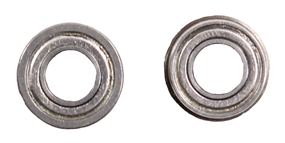
The bearing should slide smoothly (yet tightly) into the bearing pocket on the block.
The bearing will completely seat itself after you have installed and tightened the (3) socket head screws and standoffs in Step 5.
Note that the motors are mounted at an angle to the bearing blocks as shown above. This is by design, and results in a larger usable surface area on the Arlo deck, by minimizing the cutouts (for the motors) on Arlo’s main platform. There is only one orientation of the motor with the bearing block that will allow the three particular holes to line up for the bolt and standoff assemblies. This orientation is shown in the above photo which depicts the left drive unit.
This will require some “gentle, yet firm” taps from a small steel hammer. The drive pin should be centered side-to-side through the axle as shown. Be careful to not damage the (soft) aluminum axle.
Once the drive pin is installed, it is very difficult to remove. Double-check your work to be sure that you’ve done everything correctly up to this point.

You may wish to use a small piece of wood to support the axle as you “tap” the pin through the axle (above). When you’re finished, the drive pin should be centered in the axle.
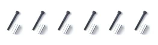
Using (3) 50 mm hex-head socket screws, and (3) 1” x 0.5” standoffs, you will now attach the motor/drive axle assembly to each of the motor bearing blocks. The screws go into three tapped holes in the motor frame. Although there are four bolt holes in the block, only three holes will be used to mount each motor.


Although there are (4) mounting holes on each of the motors (as well as the blocks), only (3) are used in each drive wheel system.
Each encoder must have a 6-pin connector soldered to its PCB. Both PCB’s are exactly the same - as are the connectors - but they are assembled in slightly different configurations.

This manner of assembly allows both sets of wires to go in the same direction from the gear head towards the back of each of the motors (as we’ll see during final assembly and mounting of the Motor Mount and Wheel assemblies).
Be sure to match the wire color with the B-R-W color-coding on the boards. The white wires will be adjacent to each other in the center of the connectors when properly attached.

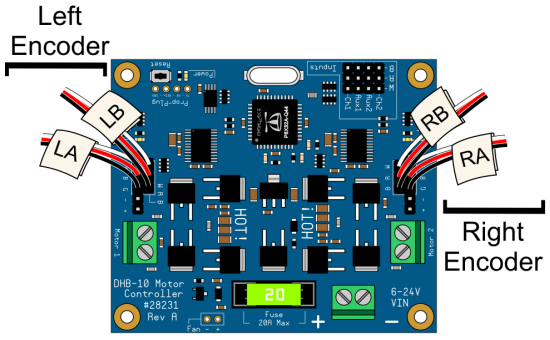
Although it's not required, labelling your cables with a small piece of masking tape (close to the unconnected ends of the cables) will make it significantly easier to make the DHB-10 connections later on in the assembly guide. Be sure to orient your encoders correctly when labelling. Left (LA, LB) and right (RA, RB) labels should correspond to your left and right sides.

The encoder board has a very tiny slotted sensor that must have the encoder wheel (that has already been installed on the drive axle) centered within its slot.

You should position the encoder boards over the encoder discs such that the discs fit in the center of the slot on the encoder sensor. The Encoder Disc should be slid tight to the axle’s “shelf” (the slightly larger diameter of the axle), as shown below.

This completes the assembly of a single motor drive unit. Duplicate what you just did for the other motor drive unit, and when you’re finished the result will be two separate motor drive units that are mirror images of each other (below)—one for each side of your robot platform. Please note that the image shown below does not show the motor units in their actual mounted configuration.

Each of the two aluminum wheel assemblies is comprised of: (1) precision machined two-piece split-rim set, (1) inner-tube, (1) rubber tire, and (6) flat-head 4-40 x ½” screws.


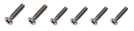
Each rim set consists of: (1) main rim, (1) rim ring, and (6) flathead #4-40 x ½” long machine screws.
WARNING! Never, ever put your fingers through the holes in the rims once the wheels are assembled. It may be tempting to carry an assembled Arlo by the wheel, but this poses a grave hazard to your fingers should the motors accidentally move the wheels.


You can choose whether to have the valve stem easily accessible from the outside of the robot (not shown), which makes it slightly easier to fill the tires if they ever need it. However, we recommend the “cleaner looking” appearance of having the stem “tucked” behind the rim, as shown here.

If you ever need to add air (very rare, if ever), you can simply remove the single bolt that holds the tire onto the motor drive axle to access the valve stem. The rim set uses #4-40 x ½” long flat head machine screws which screw directly into tapped holes from the “inside” of the aluminum main rim section. This provides for a very clean look when mounted on the Arlo Base.

The rims are precision-machined to hold the tires securely. You may have to push firmly to get the rim to fully seat itself into the hub of the rubber tire. Repeat this step for the other drive wheel.
Unless your Arlo is going to be carrying very heavy loads, there is no need to inflate the tires to their full rated capacity. Even though the tire sidewall indicates “35PSI”, we recommend no more than 10 to 15 psi for optimum traction, load carrying capacity, and shock absorption. We HIGHLY ADVISE using a bicycle hand pump (instead of a powered air compressor) to inflate the tires since the tube capacity is so small. It is very easy (and dangerous!) to over-inflate the tire using a powered air compressor.
Secure the Rims: Rim assembly best practice is to get all of the screws started into their respective threaded holes without fully securing any of them. Then, tighten each one slightly and continue this around the circle progressively tightening each screw, which will bring the two rim sections together evenly. Also, be sure to not pinch or bind the inner-tube while bringing the assembly together.
You should now have two drive assemblies that are mirror images of each other:

This completes the assembly of the Motor Mount and Wheel Kit. Set the finished drive units aside for now and go on to Section 2.
Contact Parallax sales department if any parts are missing. Otherwise, continue with the Caster Wheel Kit assembly section instructions.
Locate the triangular base plate and the swivel rod. Notice that there is a machined “flat” on the swivel rod.


The bearing on the bottom (as shown below) should simply slide in and drop into (and rest on) the bearing’s flange. Conversely, the top bearing will slide “in and up” into the bearing cavity, so that the two “flanges” are facing each other.

Once the shaft collar is installed (next Step), it will prevent the bearings from falling out.


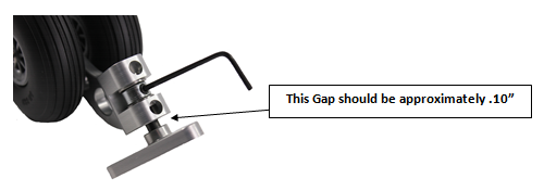
The gap between the triangular plate and the to of the swivel block should be approximately on tenth of an inch. You can make fine adjustments after they’re mounted on the Arlo deck.

The six remaining #6x3/8”socket-head screws will be used in the next Section.
The Arlo Robot Base Kit (#28960) includes an Arlo base and a double battery shelf, as well as all necessary mounting hardware for attaching the drive motor assemblies (from the Motor Mount and Wheel Kit –AL) (#28962). Each of the Caster Wheel Kit Rev. B’s (#28961) include (3) screws for mounting to the Arlo base platform.
Contact Parallax sales department if any components are missing.
The following components are also included in this Arlo Base Kit, but will not be used until Section 5. Set them aside for now.
(4) of the 710-00034 - ¼”-20 x ¾”, Flat-head socket-head screws will be used in this Section, and the remaining (4) will be used in Section 5.
You will also need the two motor assemblies from the Motor Mount and Wheel Kit (assembled in Section 1), as well as the two (assembled) Caster Wheel assemblies (from Section 2).
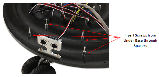
Note that the bottom of the Robot Base is the side that has the two sets of (3) caster mount “blind” holes showing. They’re “blind”, because they do not go all the way through the base platform. This results in a cleaner look on the topside of the deck and eliminates the need for nuts and washers on the top of the platform.

The main motor power wires are each going towards the large round holes just behind the rectangular cutouts (that accommodate the Motor assemblies).


WARNING! Never, ever put your fingers through the holes in the rims. It may be tempting to carry an assembled Arlo by the wheel, but this poses a grave hazard to your fingers should the motors accidentally move the wheels. Carry the Arlo by the base plate, or by the carry-handles in the top plate once it is installed.
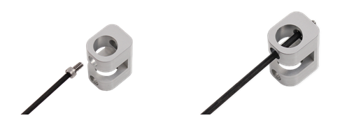
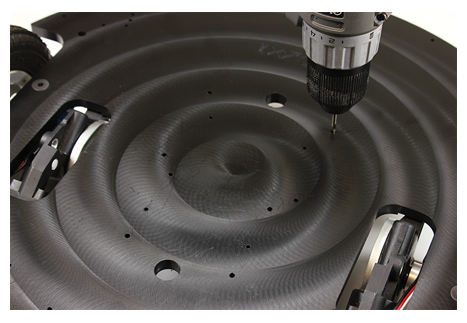
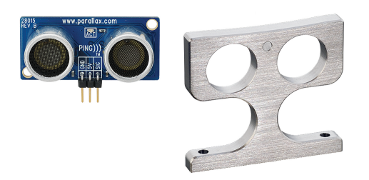
Retain the ball-end hex wrench for future use—you’ll need it when you install the PING))) Ultrasonic Distance Sensor Protector Stands. The pre-drilled screw holes are sized for self-tapping by the #6-32 socket-head machine screws.

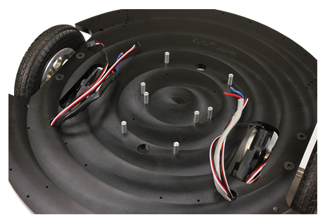
Note that some or all of the 1/8" holes in the top of the base may not be drilled all the way through. These are “blind holes” which mean they don’t go all the way through to the other side of the base platform (yet).
NOTE: If you are mounting a Board of Education Shield + Arduino as your control board, you will need to instead use the 1.25" standoffs provided in the Arlo Hardware Pack for the (4) holes closest to the front of the Arlo (top 4 standoffs in the picture below). The BOE Shield + Arduino requires more clearance than other boards and cannot be mounted on 5/8" standoffs.
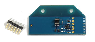
Additional information on this device can be found on its product page here [2].
For a printable copy of the Arlo Power Distribution Board instructions, download the PDF guide here [3].
Check your kit's contents with the list below before starting assembly.
Contact Parallax sales department if any parts are missing.
*The jack inner diameter size was updated May 2016. Your Arlo Complete kit will include a compatible Arlo Battery Charger. See the Arlo Power Distribution Board product guide [3] for details.
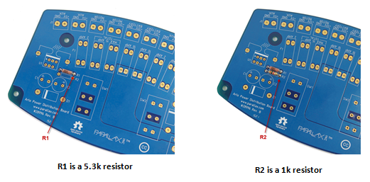
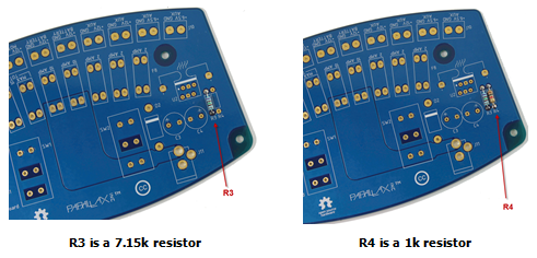
R1 has a value of 5.3k, R2&R4 are 1k, R3 is 7.15k . These resistors are non-polarized, which means that you can insert them in either direction on the board and they’ll work fine. Just be sure you put the correct values into the proper sets of holes. (You can double check the values of the resistors by using an ohmmeter.)
Note: The pictures in this section were copied from the APDB product documentation.
Important! Double-check that each resistor is in the correct location before continuing. Correct voltage output from the regulators is dependent on the resistor values being placed properly on the board.
WARNING: These parts MUST be installed in the correct direction for safety and functionality. Double-check polarity before soldering.
They should be bent accurately such that they will fit tight down to the board. A small pair of needle-nose pliers works well for this.

The fuse holders should be a friction-fit in their holes – this will help to hold them in position as you flip the board over and solder them. If they’re a looser fit, you can simply place a piece of tape across the tops of the holders to maintain their position when flipped upside down.

All of the fuse holders should be tight to the board when they’re properly soldered.
After soldering the terminal blocks, you should have something like this:


Be sure that the jack is seated tightly to the board once soldered. Due to the diameter of the holes and the flat leads that go through them, use plenty of solder to ensure that the electrical connections are entirely filled.

WARNING: These components MUST be installed in the correct orientation (see close-up below, right) - not only for proper operation, but for safety as well. Double-check orientation before soldering.
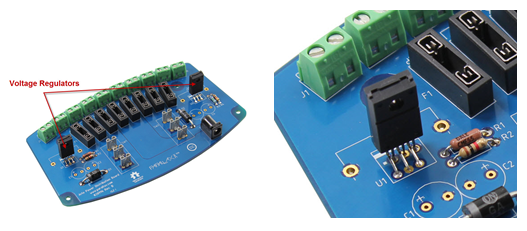
The two voltage regulators are identical, so either can be placed in their respective holes. The regulators are “programmed” to output the required voltages based on the values of each of the resistor pairs (R1, R2), and (R3-R4). For this reason, you must be certain you have installed your resistors correctly.

WARNING: These components MUST be installed in the correct orientation - not only for proper operation, but for safety as well. Check correct polarity before soldering.
Examine the board locations for C1, C2, C3, and C4, and note the markings indicating the correct polarity. You should see a plus-sign or a minus-sign on each of the capacitors themselves. The hole for each capacitor’s positive terminal is marked with a (+) on the board (below, right).
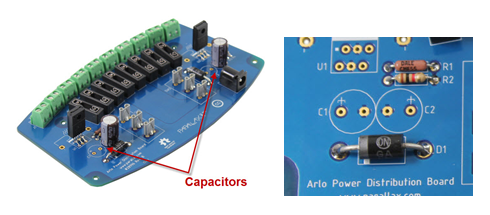
The capacitor’s negative terminal will show a (-) sign on the side of its case. Match the polarity markings on the capacitors to the markings on the PC board. Negative on the capacitor goes to negative on the printed circuit board. Note that when each set of capacitors (C1 & C2, and C3 & C4) is properly installed, they have their negative pins adjacent to each other.
Important! Do not install the capacitors backwards – if you do, they may explode when power is applied.
Properly installed, the capacitors should look like this:

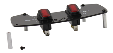
The plate is cut from .093 thick Delrin, and the text is etched into the surface. If you would like to enhance its readability, you can flood or fill the text with correction fluid (“white-out” or white paint) and then simply wipe off the excess. The fluid remains in the recessed etched lettering.
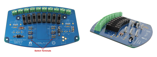
Both switches are exactly the same; therefore each can be put into either mounting hole. However, note that each switch has a bronze colored terminal (shown below) at one end (the other two terminals are silver).

Note: In the two fuse holders marked by the board label "Max 15 Amp Total", you must insert a 5A fuse into one and a 10A fuse into the other. Together they make up the 15A Total indicated by the board label.

The Battery Tray serves multiple purposes:
Even if you don’t mount your batteries on the tray, you should still attach the tray to the platform. The tray - with or without batteries - provides significant structural strength and stability to the entire system if installed.
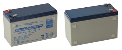
The battery tray can accommodate either one or two 12 V, 8 amp-hour sealed lead acid batteries depending on your power and load requirements. Batteries such as the PowerSonic #1270 or equivalent work well.
If you are building a two-battery system, follow these instructions and the ones at the beginning of Step 29. If you’re only going to build a one-battery system, then follow these instructions for your single battery and refer to the Single Battery Configuration instructions at the end of Step 29. The Arlo Full Kit includes both the one and two-battery system components.

Important! Make sure you tape over the uncrimped wire ends (as mentioned above) – this will help prevent any accidental shorting of the batteries until they’re ready for their final connections. Be absolutely sure you have fully covered the exposed wire. Once connected to the batteries it is very important you do not allow wire ends to touch each other!

For the Single-Battery Configuration diagram, click here or scroll to the end of this step.

Before you install anything: the (4) counter-sunk side of the mounting holes (that fasten the tray to the bottom of the motor mount blocks) should be facing down (opposite side of where the batteries and standoffs are) so that the flat head screws will seat properly when the battery assembly is connected to the motor mount and wheel assemblies.
Note: The physical size of the batteries (that are included in the Arlo Complete Robot System) may vary slightly due to battery manufacturing tolerances. Therefore, it may not be necessary or feasible to install the middle retention posts. If you choose not to install the central posts, there are other optional holes to install retention posts on the outsides of the battery tray (close to the terminals) which have been outlined in the above image with an orange box. Use the best configuration for your battery size and setup.
If you’re using the standard 12 V, 7.5 Ah sealed lead acid (SLA) batteries (that come with the Arlo Complete Robot System), the (included) 5/8” F/F standoffs and #4-40 x ½” long pan-head screws will hold them securely as shown. The staggered hole patterns accommodate slight dimensional variances between different brands of batteries. Use the (staggered) holes that provides for the tightest retention of each of the batteries.


This completes the installation of the batteries and the battery tray.
If you wish to mount a single 12 battery to the Arlo Platform instead, use the following Single-Battery Configuration shown here:

Complete battery tray installation by following the tray mounting-procedures as outlined in the double-battery configuration instructions, above.
Contact sales@parallax.com if parts or components are missing.
The Arlo Complete Robot System includes:
Each of the (4) Ping))) Sensor & Protector Stand Kits includes the following components:
You’ll also need the following parts (included in the Hardware Pack for Arlo):
and

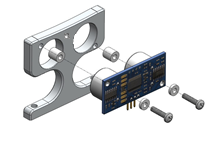
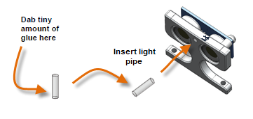
Important: Do not push the light pipe in further after you feel it touch the Ping))) – doing so could damage your Ping))) sensor!
Note: Some images and text from this assembly section were taken from the #725-28015 product guide.
Note: You can use a few zip ties to help keep them neatly in place like shown in the photo below, but you may need more zip ties for this than were provided in the kit. This is optional, but we do recommend having additional zip ties on hand for future Arlo modification.

There are (4) Ping))) (three-wire) cables: 12", 12”, 16” and 24”. The remaining (2) 4” cables will be used in Section 7. The Ping))) sensor directly in front of the right drive wheel uses the 24” 3-wire cable. The center-front sensor cable is 16” in length, and the left-front sensor uses one of the 12” cables. The rear-facing sensor uses the other 12” cable.
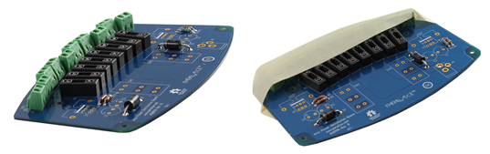
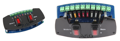
In this section, you will mount the Arlo Power Distribution Board and the DHB-10 Motor Controller board. You will also mount the development board of your choice to be the robot's main control board.
A free Propeller Activity Board WX is included in your kit, and is used as the example in the rest of this guide. But, the mounting holes in the Arlo Base also fit the BASIC Stamp + Board of Education, and the Board of Education Shield + Arduino Uno.

Note: This below image is a guide to show placement of the 4 screws and standoffs. As you install the Power Distribution Board you will have to install each screw/standoff to the PDB one at a time.


As shown above, we’re using black wires for ground, or negative battery, and we’re using yellow wires for +12 volts or positive battery power.
The DHB-10 Motor Controller runs on +12V so we’re connecting the black wire to ground and the yellow wire to the +12V terminal labeled ”Motor” that has the 10 amp fuse capability.
IMPORTANT: Observe proper polarity!
It’s now time to connect both sets of battery wires to their respective terminals.
Remember that these two sets of battery wires are already connected to the batteries. While you’re working with them, so be sure to not cause any short circuits – we don’t want to arc-weld any robot parts in this project!
Since we’re working with stranded wires, make sure these connections are solid and that there are no little tiny wires that aren't totally contained within the terminal screw cavity.
Important Tip: SLA batteries can permanently lose functionality if allowed to remain discharged or in a low-charge state for an extended period of time. It is important that SLA batteries be completely charged periodically to prevent this. We strongly recommend that you fully charge your Arlo batteries at least once per month, even when the robot is not in use.

We will only be using the jack portion for this Step – you can use the battery holder for another project if you so desire.


Why ask you to do this? Learning how to use your voltmeter gives you a valuable tool when troubleshooing issues that may arise with your Arlo robot – now or in the future.
Note: If you prefer not to have excess motor wire on your Arlo you can trim the length, or you can leave them long and just tuck the excess under the DHB-10’s PCB. How much wire to remove is up to your preference, but be careful not to cut the wires too short or they may not connect to the DHB-10 properly. Measure and double-check that your connections can still be made properly before trimming anything!
For making electrical connections specific to your control board, test code, and troubleshooting choose your board type from the list below:
If using a custom board, complete the connections and then optionally move on to Section 8: Mounting the Arlo Top Deck.
Adding the Arlo Robot Top Deck is optional, but recommended. The top deck helps to protect the electrical components mounted on the base, and gives the Arlo a cleaner, sleeker appearance. The top deck comes with additional mounting holes that provide ample area to customize and personalize your Arlo Robot.
IMPORTANT! This step should be performed after you complete the electrical connections between your control board, Ping))) sensors, and DHB-10 Controller. Mounting the top plate will restrict access to those components. Go back to the last step and choose your board type for instructions on making those connections if you haven't done so already.


This completes the Arlo mechanical assembly.

Links
[1] http://forums.parallax.com/
[2] http://www.parallax.com/product/28996
[3] https://www.parallax.com/downloads/arlo-power-distribution-board-product-guide
[4] http://learn.parallax.com/tutorials/robot/arlo/arlo-activity-board-brain
[5] http://learn.parallax.com/tutorials/robot/arlo/arlo-basic-stamp-boe-bot-brain
[6] http://learn.parallax.com/tutorials/robot/arlo/arlo-arduino-uno-boe-shield-brain