The Arlo Robot Base Kit (#28960) includes an Arlo base and a double battery shelf, as well as all necessary mounting hardware for attaching the drive motor assemblies (from the Motor Mount and Wheel Kit –AL) (#28962). Each of the Caster Wheel Kit Rev. B’s (#28961) include (3) screws for mounting to the Arlo base platform.
Contact Parallax sales department if any components are missing.
The following components are also included in this Arlo Base Kit, but will not be used until Section 5. Set them aside for now.
(4) of the 710-00034 - ¼”-20 x ¾”, Flat-head socket-head screws will be used in this Section, and the remaining (4) will be used in Section 5.
You will also need the two motor assemblies from the Motor Mount and Wheel Kit (assembled in Section 1), as well as the two (assembled) Caster Wheel assemblies (from Section 2).
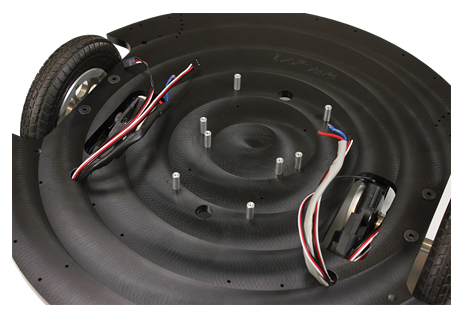
Note that the bottom of the Robot Base is the side that has the two sets of (3) caster mount “blind” holes showing. They’re “blind”, because they do not go all the way through the base platform. This results in a cleaner look on the topside of the deck and eliminates the need for nuts and washers on the top of the platform.

The main motor power wires are each going towards the large round holes just behind the rectangular cutouts (that accommodate the Motor assemblies).


WARNING! Never, ever put your fingers through the holes in the rims. It may be tempting to carry an assembled Arlo by the wheel, but this poses a grave hazard to your fingers should the motors accidentally move the wheels. Carry the Arlo by the base plate, or by the carry-handles in the top plate once it is installed.
Retain the ball-end hex wrench for future use—you’ll need it when you install the PING))) Ultrasonic Distance Sensor Protector Stands. The pre-drilled screw holes are sized for self-tapping by the #6-32 socket-head machine screws.

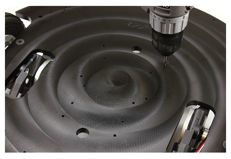
Note that some or all of the 1/8" holes in the top of the base may not be drilled all the way through. These are “blind holes” which mean they don’t go all the way through to the other side of the base platform (yet).
NOTE: If you are mounting a Board of Education Shield + Arduino as your control board, you will need to instead use the 1.25" standoffs provided in the Arlo Hardware Pack for the (4) holes closest to the front of the Arlo (top 4 standoffs in the picture below). The BOE Shield + Arduino requires more clearance than other boards and cannot be mounted on 5/8" standoffs.