If you can blink an LED, you can rule the world! Or at least illuminate it slightly :) This tutorial will help you add code to the Parallax ELEV-8 Flight Controller that will allow it to interact with other devices or electronics. This tutorial contains intermediate and advanced elements that will help you use any unused pins on your Parallax Flight Controller as general-purpose input/output pins. Once you understand how to control an LED or read the state of an input pin, you can extend that knowledge to applications such as triggering a camera shutter or data logger. Although this tutorial will use specific hardware, many of the concepts can be used with a wide range of hardware.
It is possible to complete this tutorial by simply using what comes with the ELEV-8 v3 kit and making changes to the code. The code you add to the firmware to learn how to toggle inputs and outputs is only meant to be used temporarily. If you choose to add additional electronics or hardware more permanently to your ELEV-8 v3 and/or make changes to the firmware, you will need to take special care that:
This tutorial will show you how to write and edit Propeller C code and the Flight Controller firmware using the SimpleIDE software. You will compile your code and load it into the Propeller microcontroller on the Flight Controller, then see the results.
A complete, tested, configured ELEV-8 v3 (Parallax Item #80300 [3] or Item #80330 [4]) that has a receiver with at least 6 channels, such as:
If you wish to mount hardware, sensors, or lights to the bottom chassis plate of your ELEV-8 v3, you will need hardware and/or adhesive, such as:
If you wish to complete the optional activities in this tutorial, including connecting your flight controller to an external development board, you will need:
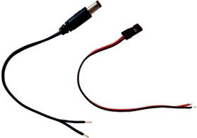
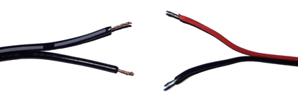
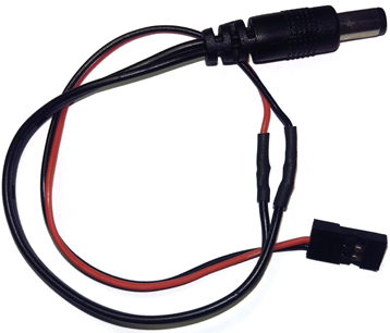
One of the easiest ways to add functionality to your ELEV-8 v3 (or any other sUAV) is to attach a development board such as an ActivityBoard [16], Board of Education [17], or Arduino + Parallax Sheild [18]. It is even possible to power any of these boards directly from the ELEV-8 v3's by building a custom adapter cable:
REMOVE the XBee, WX, or other RADIO MODULE BEFORE your proceed! This tutorial uses the indicator lights for the XBee/WX socket to demonstrate how to toggle pins, and if you leave the radio module plugged in, you will damage both the radio module and Flight Controller!
The Parallax Flight Controller has 3 status LEDs for a radio module plugged into the XBee/WX socket. If there is no radio module plugged into that socket, the LEDs can be turned on and off by the on-board Propeller Microcontroller. Here is part of the schematic for the Flight Controller. If you look carefully, there are 3 LEDs connected to P21, P22, and P23:
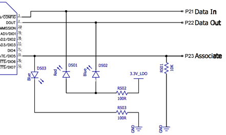

Setting P21 and P22 low will turn on those two LEDs, and Setting P23 high will turn on that LED.
Now you are ready to edit the firmware on the flight controller to turn LEDs off and on. First, you need to add a few functions to the Flight Controller Firmware.
A list of files will appear on the left side of the window.
int main()                                    // Main function
{
  Initialize(); // Set up all the objects
// Functions to set a pin's direction
void FCsetAsInput( int pinNumber ) { DIRA &= ~( 1 << pinNumber ); }
void FCsetAsOutput( int pinNumber ) { DIRA |= ( 1 << pinNumber ); }

// Functions to set the state of an output pin
void FC_low( int pinNumber ) { OUTA &= ~( 1 << pinNumber ); }
void FC_high( int pinNumber ) { OUTA |= ( 1 << pinNumber ); }
unsigned int FC_toggle( int pinNumber )
{
  OUTA ^= ( 1 << pinNumber );
  return (OUTA >> pinNumber ) & 1;
}

// Function to read an input pin
unsigned int FC_input( int pinNumber )
{
  int mask = 1 << pinNumber;                        // Set up mask
  return (INA & mask) >> pinNumber;                 // Return input state
}
// Set up the 3 pins attached to the LEDs as outputs
FCsetAsOutput(21);
FCsetAsOutput(22);
FCsetAsOutput(23);
void InitSerial(void)
{
  S4_Initialize();

  S4_Define_Port(0, 115200,      30, TXBuf1, sizeof(TXBuf1),      31, RXBuf1, sizeof(RXBuf1));
  S4_Define_Port(1,  57600, XBEE_TX, TXBuf2, sizeof(TXBuf2), XBEE_RX, RXBuf2, sizeof(RXBuf2));

  // Unused ports get a pin value of 32
  S4_Define_Port(2, 19200,       19, TXBuf3, sizeof(TXBuf3),      20, RXBuf3, sizeof(RXBuf3));
  S4_Define_Port(3, 115200, PIN_MOTOR_AUX2, TXBuf4, sizeof(TXBuf4), 32, RXBuf4, sizeof(RXBuf4));

  S4_Start();
}
The pins in the code above are not necessary for flight, but this does disable communication through the XBee/WX socket.
  if( Radio.Aile < 0 )  // Check the right transmitter stick
  {
    FC_low(21);         // Turn the red LED on
    FC_high(22);        // Turn the left blue LED off
  } else {
    FC_high(21);        // Turn the red LED off
    FC_low(22);         // Turn the left blue LED on
  }

  if( Radio.Elev < 0 )  // Check the right transmitter stick
  {
    FC_low(23);         // Turn the right blue LED off
  } else {
    FC_high(23);        // Turn the right blue LED on
  }
DO NOT CONNECT YOUR ELEV-8's Battery. Make sure the propellers have been removed from your ELEV-8 quadcopter before continuing.
Replace the Radio.Aile and Radio.Elev with some other variables:
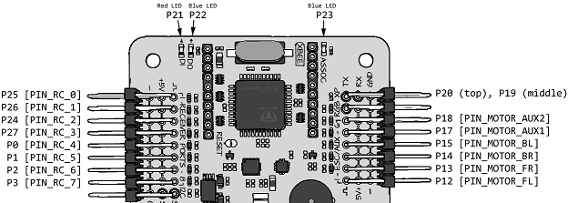
The receiver and ESC pins on the Parallax Flight Controller can be used for a number of different purposes. In addition to reading the signals coming in from the reciever and sending servo pulses to the ESCs, they can be driven high or low or be read as an input.
To read a pin, we will need to utilize 2 more of the functions, FCsetAsInput(); and FC_input(); we added to the Flight Controller firmware on the previous page:
FCsetAsInput( int pinNumber );
int pinState = FC_input( int pinNumber );
The first function, FCsetAsInput();, when used near the the beginning of the firmware's code, sets a pin to be an input. The second function reads the pin, and its result can be placed in a variable to be used later. The diagram below shows the pin numbers and names available in the firmware:
A list of files will appear on the left side of the window.
// Set up the 3 pins attached to the LEDs as outputs
FCsetAsOutput(21);
FCsetAsOutput(22);
FCsetAsOutput(23);
FCsetAsInput(1);
FCsetAsInput(2);
FCsetAsInput(3);
  if( FC_input(1) == 1 )  // Check the P1 pin
  {
    FC_low(21);      // Turn the red LED on
  } else {
    FC_high(21);     // Turn the red LED off
  }

  if( FC_input(2) == 1 )  // Check the P2 pin
  {
    FC_low(22);      // Turn the left blue LED on
  } else {
    FC_high(22);     // Turn the left blue LED off
  }

  if( FC_input(3) == 1 )  // Check the P3 pin
  {
    FC_high(23);     // Turn the left blue LED on
  } else {
    FC_low(23);      // Turn the left blue LED off
  }
DO NOT CONNECT YOUR ELEV-8's Battery. Make sure the propellers have been removed from your ELEV-8 quadcopter before continuing.

When you make connections, the corresponding indicator LEDs on the Flight Controller board will turn on.
You can do more than just blink the LEDs attached to the ELEV-8 Flight Controller - you can connect the flight controller to an external LED, or even another development board like the Activity Board or an Arduino!
Although this part of the tutorial is optional, it is helpful to see how the flight controller can be programmed to control an external accessory such as a data-logging sensor.
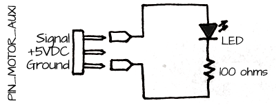
Instead of turning on an LED on the Flight Controller itself, let's try turning on an external LED - this will demonstrate that the pins on the flight controller can be connected to external devices.
// Set up the 3 pins attached to the LEDs as outputs
FCsetAsOutput(21);
FCsetAsOutput(22);
FCsetAsOutput(23);
FCsetAsInput(1);
FCsetAsInput(2);
FCsetAsInput(3);
FCsetAsOutout( PIN_MOTOR_AUX1 );
  if( Radio.Gear < -512  )  // Check the gear(mode) switch position
  {
    FC_low( PIN_MOTOR_AUX1 );      // Turn the external LED of
  } else {
    FC_high( PIN_MOTOR_AUX1 );     // Turn the external LED on
  }
DO NOT CONNECT YOUR ELEV-8's Battery. Make sure the propellers have been removed from your ELEV-8 quadcopter before continuing.
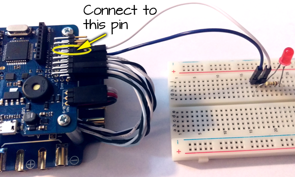
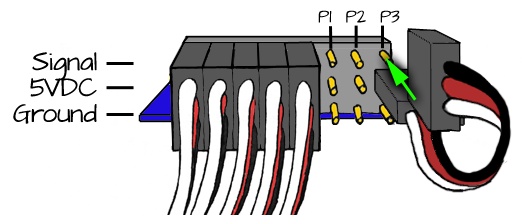
If you wish to connect another development board such as an Activity Board or an Arduino to your ELEV-8 v3, you will need a way to power that board.
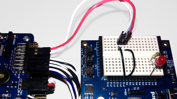
Although this example is specific to an Activity Board, the same concepts can be used to connect and Arduino or even a BASIC Stamp development board.
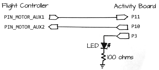
In this example of two-way communication, when the gear (mode) switch is flipped on, the Flight Controller sets one of its pins high. This pin, which is connected to an Activity Board, tells the Activity Board to begin its program. The Activity Board then turns on 3 LEDs in 3 seconds. Then, the Activity Board sets one of its pins, which is connected back to the Flight Controller, high. When the Flight Controller detects that that pin is high, it turns on one of its on-board LEDs.
This application is especially useful because the Activity Board has an SD card slot and is able to do data-logging with any sensor that you are able to attach to it. Click here for a tutorial on using the Activity Board to record data to an SD card. [24]
// Set up the 3 pins attached to the LEDs as outputs
FCsetAsOutput(23);
FCsetAsOutput(PIN_MOTOR_AUX1);
FCsetAsInput(PIN_MOTOR_AUX2);
  if( Radio.Gear < -512  )             // Check the gear(mode) switch position
  {
    FC_low( PIN_MOTOR_AUX1 );          // Turn off the Activity Board trigger
  } else {
    FC_high( PIN_MOTOR_AUX1 );         // Turn on the Activity Board trigger
  }

  if( FC_input(PIN_MOTOR_AUX2) == 1 )  // Check if the Activity Board is sending a signal
  {
    FC_low(23);                        // Turn on the on-board LED
  } else {
    FC_high(23);                       // Turn off the on-board LED
  }
DO NOT CONNECT YOUR ELEV-8's Battery. Make sure the propellers have been removed from your ELEV-8 quadcopter before continuing.
#include "simpletools.h"                      // Include simple tools

int main()                                    // Main function
{
  // Add startup code here.
  while(1)
  {
    low(26);                 // make sure all LEDs
    low(27);                 // and the Flight Controller
    low(3);                  // trigger are off
    low(10);

    if(input(11) == 1)       // Did the flight controller send
    {                        // a high signal?
      high(26);              // Turn on the first LED
      pause(1000);           // Wait 1 second
      high(27);              // Turn on the second LED
      pause(1000);           // Wait 1 second
      high(3);               // Turn on the third LED
      pause(1000);           // Wait 1 second
      high(10);              // Send a signal to the Flight Controller

      while(input(11) == 1); // Wait until the Flight Controller stops
    }                        // sending a high signal
  }
}
The next few pages in this tutorial provide a little coding background info that can help you with your ELEV-8 hacking.
If you've programmed the Programmed the Propeller Multicore Microcontroller on the Activity Board or ActivityBot robot, you have have used some functions like:
high(5);
low(4);
button = input(3);
pause(500);
These functions make it easy to do things such as turn on or blink an LED or read a pushbutton. You can use these functions whenever you have #include "simpletools.h" at the top of your program.
These functions are essentially convenience functions, and they make your code a lot simpler. 99% of the time, they are fast enough for your application and do exactly what you need them to do. On the ELEV-8 v3, where a LOT has to happen VERY quickly, these functions are simply too slow - or in the case of the pause() function, stop the program entirely while the pause waits to complete.
In order to learn how to set pins high or low without simpletools.h, or set them as inputs and read their state, we have to learn a few things about the Propeller and a little bit about bitwise operators.
We are used to seeing numbers represented using digits, specifically base-10 digits. When we count, we say "1..2..3..4..5..6..7..8..9..10.." and so on. We probably developed this as a counting system because we have ten fingers. At its core, a microprocessor like the Propeller is made up of thousands of transistors, and they can only be on or off. When a computer or microprocessor counts with its "fingers", it only has two to work with. Here is a comparison of how a person and a microprocessor count to 20:
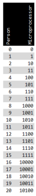
We humans roll over to the next digit when we hit 10, then 20, 30, and so on. A microprocessor rolls over after each 1 - every two times. This counting system is called binary or base-2. Once you understand it, it's incredibly useful.
Let's start with the number 1. In binary, it's still just 1. Just like with the decimal numbers we are used to, if we put a bunch of zeros in front of it, it won't change the value. 0000245 is the same as 245. If you put a bunch of numbers in front of a binary number, it won't change the value. It will, however, help you understand how binary numbers are stored inside the Propeller.
The Propeller microcontroller is a 32-bit processor. When it does an operation, it does it with 32 bits at a time. One of the easiest operations to understand is bit shifting. If we start with the number one with all 32 bits written out, it looks like this (spaces are added to make it easier to read):
0000 0000 0000 0000 0000 0000 0000 0001
Now, we are going to left shift that number 1 space:
0000 0000 0000 0000 0000 0000 0000 0010
If you look at the table above, the binary number 10 is equal to the decimal number 2. Let's shift it left 2 more spaces (3 total):
0000 0000 0000 0000 0000 0000 0000 1000
If you look at the chart above, this is equal to the decimal number 8. If you are good with math, you may have noticed that 8 is 2 × 2 × 2. Every time we shift to the left, it's the same as multiplying by 2!
We can go the other way as well. If we start with 1000, and right shift it 2 times, we get 0010. We went from 8 to 2. Right shifting is basically dividing by two: 8 ÷ 2 ÷ 2 = 2.
When we are writing programs, we can use the symbols << to left shift and >> to right shift a number.
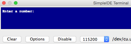
Here is a program that lets you try shifting numbers left and right. Open SimpleIDE and connect your Flight Controller to your computer.
Open a new C project, copy the code below, and paste it into SimpleIDE:
/*
Bit shifting example
*/

#include "simpletools.h"                           // Include simpletools library

int theNumber;                                     // Declare variables
char shiftDirection;
int shiftAmount;

int main()                                         // Main function
{
  while(1)
  {
    print("Enter a number: ");                     // User prompt to enter the number
    scan("%d\n", &theNumber);                      // Scan what the user types

    print("Enter \"<\" to shift left and \">\" to shift right: ");
    scan("%c\n", &shiftDirection);

    print("Enter the amount to shift: ");
    scan("%d\n", &shiftAmount);

    print("\n(%d)\t%b %c%c %d = ", theNumber, theNumber, shiftDirection, shiftDirection, shiftAmount);

    if( shiftDirection == '<' )                    // Determine which way to shift
    {                                              // the number
      theNumber = theNumber << shiftAmount;        // Left shift
    } else {
      theNumber = theNumber >> shiftAmount;        // Right shift
    }

    print("%b\t(%d)\n\n", theNumber, theNumber);   // Print the shifted number
  }
}
Plug your Flight Controller into your computer, make sure the right port is selected, and click Program > Run with Terminal. You will see this:
Type in a number and hit enter. Then type "<" or ">" to shift the number left or right. Then type a number representing how much to shift the number.
Your result will look something like this:
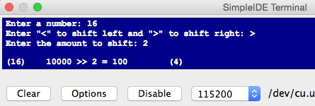
Try different combinations of numbers, directions, and amounts until you have a better understanding of how binary numbers and bit shifting work.
Since binary digits represent "On" and "Off", we can use operators with them that reflect real-world operations - think about switches and light bulbs.
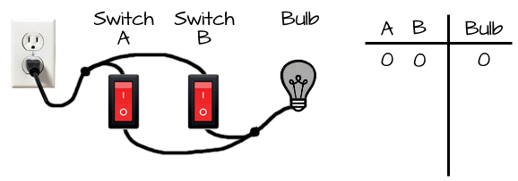
If we have two switches and a light bulb to tell us if something is on or off, we can represent concepts like AND and OR. Let's start with AND.
Look carefully at the diagram below. In order for the light to come on, BOTH switches have to be turned on:
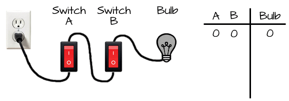
If we AND to binary numbers, a bit has to be 1 in both numbers for the bit to be a 1 in the new number.
The symbol for AND'ing two numbers is "&". Here is an example of two binary numbers being AND'ed together:
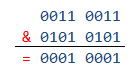
The only digits that remain as 1's are the digits where there was a 1 in both numbers.
OR can be used similarly. Take a look at the diagram below. Only one of the switches needs to be on to turn on the light:
If we OR two binary numbers, only one of the bits has to be a 1 for the bit to be a 1 in the new number.
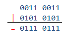
The symbol for OR'ing two numbers is "|". Here is an example of two binary numbers being OR'ed together:
/*
AND and OR operators example
*/

#include "simpletools.h"                           // Include simpletools library

unsigned int numberA;                              // Declare variables
unsigned int numberB;
unsigned int numberC;

int main()                                         // Main function
{
  while(1)
  {
    // Prompt user to enter two binary numbers
    print("Enter a binary number (up to 8 digits): ");
    scan("%b\n", &numberA);
    print("Enter another binary number (up to 8 digits): ");
    scan("%b\n", &numberB);

    // Display the results AND'ed together
    print("\n\nAND example:\n");
    print("\t  %08b\n\t& %08b\n\t__________\n", numberA, numberB);

    numberC = numberA & numberB;                   // AND the numbers together

    print("\t= %08b", numberC);

    // Display the results OR'ed together
    print("\n\nOR example:\n");
    print("\t  %08b\n\t| %08b\n\t__________\n", numberA, numberB);

    numberC = numberA | numberB;                   // OR the numbers together

    print("\t= %08b\n\n", numberC);
  }
}
You should se something like this:

Now that we know a litle bit about shifting, inverting, AND'ing and OR'ing, we can start using that knowledge to turn the pins of the Propeller microcontroller on and off or read them as inputs. The Propeller multicore microcontroller has 32 GPIO pins, which stands for "General Purpose Input/Output." Because it is a 32-bit processor, it can fit all of those pins into a single port. Other microcontrollers have multiple ports, often labeled PORTA, PORTB, etc. On the Propeller, there is only a port A.

The port has several pin control registers:
If we want to set pins 0-15 as inputs and pins 16-31 as outputs, we could type this line of code into our program:
DIRA = 0b11111111111111110000000000000000;
So, how do we change one pin at a time? This is where using shifting, inverting, AND'ing and OR'ing come in handy.
Let's set pin P3 as an output and leave all of the other pins as they are. This means we need bit 4 to be a 1. This code will do just that - it sets P3 to a 1 without changing any of the other pins:
DIRA = DIRA | 0b00000000000000000000000000001000;
Here's why this works: If you take any bit and OR it with a zero (0), it will stay the same. If you OR the number with a one (1), it will become a one (1).
Now let's try to make the line of code simpler and more useful:
DIRA |= (1 << 3);
Two things were simplified. The first is replacing DIRA = DIRA | .... with DIRA |=. It's a shorthand trick that gives the same result. This can be done with other operands too: +=, -=, *=, &=, |= are just a few. You can find a complete list by going here [25] and scolling down to "Assignment Operators". The other thing that was simplified was to create the binary number 1000 by taking the number 1 and left shifting it 3 places. This means that if we want to build a useful function, we could do this:
DIRA |= ( 1 << pinNumber );
This will set whatever number we assign to pinNumber as an output.
Let's try setting a pin as an input. This means that we need a specific pin to be a 0, and we need to leave every other pin alone. If we AND something with a 1, it will stay the same, and if we AND it with a zero, it will become a zero. This means that to set pin P3 to be an input, we would type:
DIRA = DIRA & 0b11111111111111111111111111110111;
We can create the big long binary number by inverting 00000000000000000000000000001000, and we can create that number by shifting a 1 to the left 3 places:
DIRA = DIRA & ~( 1 << 3 );And if we replace the 3 with pinNumber and use the shorthand operator:
DIRA &= ~( 1 << pinNumber );
Now we have a way to set an input and to set an output. We can build two useful functions:
void FCsetAsInput( int pinNumber ) { DIRA &= ~( 1 << pinNumber ); }
void FCsetAsOutput( int pinNumber ) { DIRA |= ( 1 << pinNumber ); }We can use the same tricks we used to set pins as inputs or outputs on a different register, the OUTA register, so set the state of an output pin.
If we replace the DIRA with OUTA in the the functions we wrote earlier, we can build two new useful pin setting functions:
void FCsetPinLow( int pinNumber ) { OUTA &= ~( 1 << pinNumber ); }
void FCsetPinHigh( int pinNumber ) { OUTA |= ( 1 << pinNumber ); }This one gets a little trickier. Instead of setting a register, we are reading it. Look at the picture at the top of this page again. Each pin corresponds to a bit in the INA register, so if we were to read the INA register, we might get something that looks like this:
10101010011011111011101010111101
If we are only interested in pin P3, we need to create a mask and then AND the INA register with that mask:

To create the mask, we can shift 1 to the left 3 positions, and to get the result, we can shift it to the right 3 positions. Now we can create a function that reads the input of any pin:
int FCreadPin( int pinNumber )
{
  int mask = 1 << pinNumber;                        // Set up mask
  return (INA & mask) >> pinNumber;                 // Return input state
}Now that you have modified the hardware and/or firmware for the ELEV-8 v3, it is necessary to test its functionality to make sure it is safe to fly. Yes, do this every time you made hardware and/or firmware modifications!
DO NOT SKIP THIS PROCEDURE! Flying with untested firmware is dangerous and can cause severe injury or property damage or loss.
If you have not done so already, REMOVE YOUR PROPELLERS before proceeding!
If your ELEV-8 v3 fails to pass any of the steps below, STOP - disconnect the ELEV-8 v3's battery and return to prior steps to begin troubleshooting the problem.
Pay close attention to the RGB LED on the Flight Controller. During this process, it should continue to flash/alternate colors. Except during power-up, arming and disarming, if the LED stops flashing, there is a problem with your code and it is not safe to fly.
The Propeller microcontroller on the Flight Controller has a system clock that takes approximately 53 seconds to roll back over to zero and start again. Testing for 90 seconds ensures that the rollover will not cause a lock-up.
If your ELEV-8 v3 passed all of the above tests, it should be safe to re-install the propeller blades when you are ready to fly.
For your first flight with modified firware and hardware, follow all safety precautions.
Fly gently, close to the ground, and away from any people, objects, or structures until you are confident that your ELEV-8 v3 is performing normally.

Links
[1] https://learn.parallax.com/propeller-c-set-simpleide
[2] http://learn.parallax.com/elev-8-v3-quadcopter-assembly-guide/step-23-install-or-update-firmware
[3] https://www.parallax.com/product/80300
[4] https://www.parallax.com/product/80330
[5] https://www.parallax.com/product/80206
[6] https://www.parallax.com/product/80208
[7] https://www.parallax.com/product/730-80300
[8] https://www.parallax.com/product/570-80300
[9] https://www.parallax.com/product/570-35000
[10] https://www.parallax.com/product/720-00011
[11] https://www.parallax.com/product/800-00080
[12] https://www.parallax.com/product/800-00120
[13] https://www.parallax.com/product/451-00303
[14] https://www.parallax.com/product/800-00046
[15] https://www.parallax.com/product/800-00048
[16] https://www.parallax.com/product/32912
[17] https://www.parallax.com/product/28850
[18] https://www.parallax.com/product/35000
[19] http://www.digikey.com/product-detail/en/tensility-international-corp/CA-2185/CP-2185-ND/568576
[20] https://www.parallax.com/product/700-10011
[21] https://www.parallax.com/product/910-27200
[22] https://www.parallax.com/product/700-10001
[23] https://www.parallax.com/product/700-10002
[24] http://learn.parallax.com/propeller-c-simple-devices/sd-card-data
[25] http://www.tutorialspoint.com/cprogramming/c_operators.htm