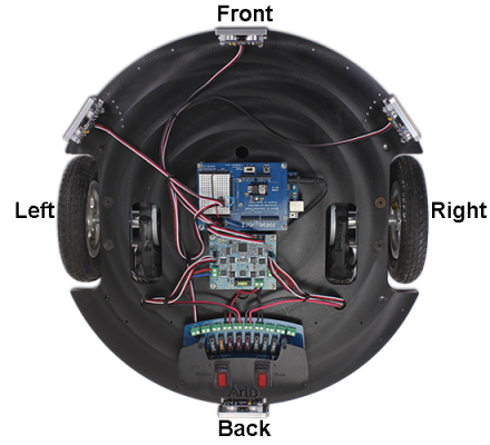
Ready for a bigger Arduino-powered BOE Shield-Bot? Try mounting your Board of Education Shield with an Arduino Uno on the Arlo! After a couple connections and a few simple tests, any Shield-Bot code will run. The time it takes for the Arlo to go distances and execute turns is different, so you will have to adjust some numbers in your sketches, but after that the Arlo will run Shield-Bot code like a champ.
First, you will need the ArloRobot library and programming software for the Arduino Uno to run these example programs.
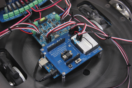
The BOE Shield connections to the Arlo’s DHB-10 motor control board use the same servo ports as the ones you used to connect to your Shield-Bot’s servos.

Let's run an number of tests to make sure the electrical connections are correct before trying to run the Arlo, starting with the battery.
IMPORTANT: If you have not already done so, make sure your batteries are freshly charged. Follow the instructions on the charger case. Batteries should be recharged to 12.6 V before they discharge below 12 V.
Let’s make sure to clear the sketch in the Arduino before turning Motors power on. That way, some BOE Shield-Bot sketch that used to be in there won’t send your Arlo into unexpected maneuvers.
/*
Arlo-No-Surprise-Maneuvers.ino
Run this before ever turning on power to the Arlo's motors to prevent any
unexpected motions.
*/

void setup()                                   // Setup function
{
 tone(4, 3000, 2000);                          // Piezospeaker beep
 Serial.begin(9600);                           // Start terminal serial port
 Serial.print("Your Arlo will stay still.");   // Message
}

void loop() {}                                  // Nothing for main loop
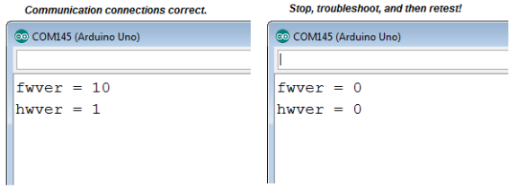
This next sketch asks the DHB-10 for its hardware and firmware versions, and displays the results in Terminal. Here is what you’ll see if your Arduino communicates successfully with the DHB-10 (left) alongside messages you might see if communication fails (right).
IMPORTANT: Your Arlo will not be ready for the next step until it displays nonzero values for fwver and hwver.
NOTE: If your terminal output resembles the one on the right, try the Arlo Failed the Communication Test section in Troubleshooting [5].
/*
Arlo-Test-Arduino-DHB-10-Communication
You'll be ready for the next step when the Arduino Terminal displays:
fwver = 10
hwver = 1
*/

#include <ArloRobot.h>                     // Include Arlo library
#include <SoftwareSerial.h>                   // Include SoftwareSerial library

ArloRobot Arlo;                            // Declare Arlo object

SoftwareSerial ArloSerial(12, 13);            // Declare SoftwareSerial object
                                              // DHB-10 -> I/O 12, DHB-10 <- I/O 13
void setup()                                  // Setup function

{
 tone(4, 3000, 2000);                        // Piezospeaker beep
 Serial.begin(9600);                         // Start terminal serial port

 ArloSerial.begin(19200);                    // Start DHB-10 serial communication
 Arlo.begin(ArloSerial);                     // Pass to Arlo object

 int fwver = Arlo.readFirmwareVer();         // Check DHB-10 firmware
 Serial.print("fwver = ");                   // Display firmware version
 Serial.println(fwver, DEC);

 int hwver = Arlo.readHardwareVer();         // Check DHB-10 hardware
 Serial.print("hwver = ");                   // Display hardware version
 Serial.println(hwver, DEC);
}

void loop() {}                                // Nothing for main loop
This next sketch sets the Arlo’s motors to 20/127 of full power in the forward direction. If your Arlo goes forward while running this sketch, it indicates that your motors are connected correctly and the battery is charged.
IMPORTANT: Your Arlo will not be ready for the next step until it goes forward for this test.
/*
Arlo-Test-Motor-Connections
Run this sketch to verify that your Arlo goes forward.
*/

#include <ArloRobot.h>                       // Include Arlo library
#include <SoftwareSerial.h>                  // Include SoftwareSerial library

ArloRobot Arlo;                              // Declare Arlo object
SoftwareSerial ArloSerial(12, 13);           // Declare SoftwareSerial object

                                             // DHB-10 -> I/O 12, DHB-10 <- I/O 13

void setup()                                 // Setup function

{
 tone(4, 3000, 2000);                        // Piezospeaker beep
 Serial.begin(9600);                         // Start terminal serial port

 ArloSerial.begin(19200);                    // Start DHB-10 serial communication
 Arlo.begin(ArloSerial);                     // Pass to Arlo object

 Arlo.writeMotorPower(20, 20);               // Go forward very slowly
 delay(3000);                                //   for three seconds
 Arlo.writeMotorPower(0, 0);                 //   then stop
}

void loop() {}                                // Nothing for main loop
The Arlo has built-in encoders that can count how far the Arlo travels in terms of 144ths of a wheel revolution. Although it’s not needed to run BOE Shield-Bot code, it’s best to make sure they are functioning correctly in case you want to improve the accuracy of the Arlo’s maneuvers later. The next sketch will display the status of your encoder connections in the Terminal. If there is a problem, it may indicate that the encoder cables have been swapped or that there is some other wiring problem. Here are examples of what you might see:

/*
Arlo-Test-Encoder-Connections

This sketch tests to make sure the Arlo's wheel encoder connections
are correct.  The Arlo will not be ready for the next step until you
have verified that the number of encoder transitions (ticks) for both
wheels are positive when the wheels roll forward.

If you have not already completed Test Arlo Motor Connections.c,
complete it first, then continue from here.

Use the Arduino IDE’s Upload button to run this sketch.  If the
Terminal displays the "Encoder connections are correct!..."
message, your Arlo is ready for the next step, which is running
navigation sketches.

If the Terminal instead displays one or more "ERROR..."
messages, those encoder encoder connections will need to be
corrected.  For example, if the messages says, "ERROR: Motor 1
encoder connections are reversed!", you will need to unplug and
swap the two 3-wire encoder cables next to the Motor 1 terminal
on the DHB-10, swap them, and plug them back in.

Make sure to test between each adjustment.  Your arlo will not be
ready for the next step until you get the success message from
this test.
*/

#include <ArloRobot.h>                     // Include Arlo library
#include <SoftwareSerial.h>                   // Include SoftwareSerial library

// Arlo and serial objects required
ArloRobot Arlo;                            // Arlo object
SoftwareSerial ArloSerial(12, 13);            // Serial in I/O 12, out I/O 13

int countsLeft, countsRight;                  // Encoder counting variables
void setup()                                  // Setup function
{
tone(4, 3000, 2000);                        // Piezospeaker beep
Serial.begin(9600);                         // Start terminal serial port

 ArloSerial.begin(19200);                    // Start DHB-10 serial com
Arlo.begin(ArloSerial);                     // Pass to Arlo object

 Serial.println("Testing...");               // Display testing message

 Arlo.clearCounts();                         // Clear encoder counts

 Arlo.writeMotorPower(32, 32);               // Go forward very slowly
delay(4000);                                //   for three seconds
Arlo.writeMotorPower(0, 0);                 //   then stop

 countsLeft = Arlo.readCountsLeft();         // Get left & right encoder counts
countsRight = Arlo.readCountsRight();

 Serial.print("countsLeft = ");              // Display encoder measurements
Serial.print(countsLeft, DEC);
Serial.print(", countsRight = ");
Serial.println(countsRight, DEC);
Serial.println();

 // Both distances positive?
if((countsLeft > 175) && (countsLeft < 325)
&& (countsRight > 175) && (countsRight < 325))
{
   // Success message
   Serial.println("Encoder connections are correct!");
   Serial.println("Your Arlo is ready for the next step.");
   Serial.println();
}
else
{
   // Left encoders cables correct?
   if(countsLeft > 175 && countsLeft < 325)
   {
     // Correct encoder message
     Serial.println("Motor 1 encoder cables are connected");
     Serial.println(" correctly.");
     Serial.println();
   }
   // Left encoders cables swapped?
   else if(countsLeft > -325 && countsLeft < -125)
   {
     // Swapped encoder message
     Serial.println("ERROR: Motor 1 encoder connections");
     Serial.println(" are reversed!");
     Serial.println();
   }
   else                                      // Other problem
   {
     // Other encoder error message
     Serial.println("ERROR: Motor 1 encoder values out of ");
     Serial.println("range. Recheck encoder connections ");
     Serial.println("and assemblies.");
     Serial.println();
   }
   // Right encoders cables correct?
   if(countsRight > 175 && countsRight < 325)
   {
     // Correct encoder message
     Serial.println("Motor 2 encoder cables are ");
     Serial.println("connected correctly.");
     Serial.println();
   }
   // Right encoders cables swapped?
   else if(countsRight > -325 && countsRight < -125)
   {
     // Swapped encoder message
     Serial.println("ERROR: Motor 2 encoder connections ");
     Serial.println("are reversed!");
     Serial.println();
   }
   else                                      // Other problem
   {
     // Other encoder error message
     Serial.println("ERROR: Motor 2 encoder values ");
     Serial.println("out of range. Recheck encoder ");
     Serial.println("connections and assemblies.");
     Serial.println();
   }
}

 Arlo.writePulseMode();                      // Get ready for pulse control

 Serial.print("Test done.\n\n");             // Display status
}


void loop() {}                                // Nothing for main loop
Let’s try the ForwardLeftRightBackward.ino sketch from http://learn.parallax.com/node/219 in Robotics with the BOE Shield-Bot web book. You might have noticed that the second to last call in the previous sketch: Arlo.writePulseMode().. That switched the Arlo’s DHB-10 from serial communication mode to pulse mode in preparation for this sketch. When the Arlo’s DHB-10 starts up, it automatically goes into pulse mode. So, another option for switching a sketch out of serial communication mode is to simply restart the DHB-10. You can do that by either pressing and releasing its reset button or turning Motors power off and back on.
The sketch would make a BOE Shield-Bot turn about 90 degrees, but not so with the Arlo.
In the More Precise Maneuvers with Encoders section, we’ll get those 90° turns on the first try!
// Robotics with the BOE Shield - ForwardLeftRightBackward
// Move forward, left, right, then backward for testing and tuning.

#include <Servo.h>                           // Include servo library

Servo servoLeft;                             // Declare left and right servos
Servo servoRight;

void setup()                                 // Built-in initialization block
{
  tone(4, 3000, 1000);                       // Play tone for 1 second
  delay(1000);                               // Delay to finish tone

  servoLeft.attach(13);                      // Attach left signal to pin 13
  servoRight.attach(12);                     // Attach right signal to pin 12

  // Full speed forward
  servoLeft.writeMicroseconds(1700);         // Left wheel counterclockwise
  servoRight.writeMicroseconds(1300);        // Right wheel clockwise
  delay(2000);                               // ...for 2 seconds

  // Turn left in place
  servoLeft.writeMicroseconds(1300);         // Left wheel clockwise
  servoRight.writeMicroseconds(1300);        // Right wheel clockwise
  delay(600);                                // ...for 0.6 seconds

  // Turn right in place
  servoLeft.writeMicroseconds(1700);         // Left wheel counterclockwise
  servoRight.writeMicroseconds(1700);        // Right wheel counterclockwise
  delay(600);                                // ...for 0.6 seconds

  // Full speed backward
  servoLeft.writeMicroseconds(1300);         // Left wheel clockwise
  servoRight.writeMicroseconds(1700);        // Right wheel counterclockwise
  delay(2000);                               // ...for 2 seconds

  servoLeft.detach();                        // Stop sending servo signals
  servoRight.detach();
}

void loop()                                  // Main loop auto-repeats
{                                            // Empty, nothing needs repeating
}
The DHB-10 defaults to a speed control scale from 1000 to 2000 us. That’s writeMicroseconds() duration values from 1000 (full speed clockwise) to 1500 (stop) to 2000 (full speed counterclockwise). The DHB-10 has a scale command for adjusting that range. For example SCALE 200 would make it fit PULSOUT durations from 1300 to 1700. The result, the Arlo goes a lot faster! This also means it’ll travel and turn more for a given number of pulses, so some recalibration may be in order.
/*
  Arlo-Change-Pulse-Scale

  Change pulse scale from 1000...2000 us to 1300 to 1700 us so that
  Robotics with the BOE Shield-Bot examples can run the Arlo at top speed.
*/

#include <ArloRobot.h>                        // Include Arlo library
#include <SoftwareSerial.h>                   // Include SoftwareSerial library

// Arlo and serial objects required
ArloRobot Arlo;                               // Arlo object
SoftwareSerial ArloSerial(12, 13);            // Serial in I/O 12, out I/O 13

void setup()                                  // Setup function
{
  tone(4, 3000, 2000);                        // Piezospeaker beep
  Serial.begin(9600);                         // Start terminal serial port

  ArloSerial.begin(19200);                    // Start DHB-10 serial com
  Arlo.begin(ArloSerial);                     // Pass to Arlo object

  Arlo.writeConfig("SCALE", 200);             // Change pulse to speed response
  //Arlo.writeConfig("SCALE", 1000);          // Want default back?  Un-comment
  Arlo.storeConfig("SCALE");                  // Save setting in EEPROM

  Arlo.writePulseMode();                      // Get ready to receive pulses
}

void loop() {}                                // Nothing for main loop
You can also communicate with the Arlo through the Terminal. The example shown here uses rst to reset the Arlo’s encoder counts to 0. It’s the equivalent of Arlo.clearCounts(). Next, go 32 32 sets the motor power of both motors to 32/127. It’s the equivalent of Arlo.writeMotorPower(32, 32). After some time went by, go 0 0 was typed in to stop the wheels, then dist, which got a reply of 344, 348. Those are encoder measurements of the number of 144ths of a revolution each wheel turned. These values can also be obtained in a sketch with longVariable = Arlo.readCountsLeft() and longVariable = Arlo.readCountsRight().

NOTE: The reply values to your DIST command will depend on how long you let the wheels run.
/*
Arlo-Terminal-Communication
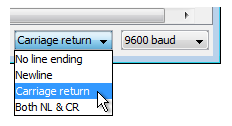
IMPORTANT: Set Line Ending to Carriage return in the terminal.
*/
#include <ArloRobot.h> // Include Arlo library
#include <SoftwareSerial.h> // Include SoftwareSerial library
// Arlo and serial objects required
ArloRobot Arlo; // Arlo object
SoftwareSerial ArloSerial(12, 13); // Serial in I/O 12, out I/O 13
char str[64];
void setup() // Setup function
{
tone(4, 3000, 2000); // Piezospeaker beep
Serial.begin(9600); // Start terminal serial port
ArloSerial.begin(19200); // Start DHB-10 serial com
Arlo.begin(ArloSerial); // Pass to Arlo object
Serial.println("Arlo Terminal"); // Display heading
}
void loop() // Main loop
{
memset(str, 0, 64); // Clear the buffer
Serial.print("> "); // Display prompt
while(Serial.available() == 0); // Wait for terminal input
Serial.readBytesUntil('\r', str, 64); // Read until carriage return
Serial.println(str); // Display what was typed
ArloSerial.print(str); // Send to Arlo's DHB-10
ArloSerial.write('\r'); // Append with a carriage return
memset(str, 0, 64); // Clear the buffer again
ArloSerial.readBytesUntil('\r', str, 64); // Get Arlo's reply
Serial.println(str); // Display Arlo's reply
}
As mentioned earlier, the Arlo has encoders that track distance in 144th increments of a full wheel rotation. These increments are commonly called “counts”, and the Arlo’s encoders send 144 counts per wheel revolution. The Arlo’s encoders are quadrature, meaning that the two encoder sensors are offset by ¼ of a count. The most important feature of quadrature encoding is that DHB-10 can determine which direction a wheel is turning by monitoring the pattern of low-high-low transitions for both sensors, the. For a given wheel, 144 counts would mean a full forward rotation, and -144 counts would mean a full backward rotation.
The Arlo’s DHB-10 motor controller has a built-in control system that uses the encoder outputs to control motor speed and distance as well as monitor motor position. The ArloRobot library has functions your sketch can call to both control speed and distance traveled, as well as poll current speed and distance.
NOTE: For more info on ArloRobot functions for Arduino, see the ArloRobot API (coming soon).
IMPORTANT: Make sure your sketch gives each maneuver enough time to finish before issuing a new distance command.
This example sketch uses the ArloRobot writeCounts function to tell the Arlo’s DHB-10 controller to make the Arlo travel certain numbers of encoder ticks, and the readCountsLeft and readCountsRight functions to check the actual distances traveled between each maneuver.
/*
Arlo-Distance-Maneuvers
Examples that use serial communication to make the arlo travel in certain
distances.
*/


#include <ArloRobot.h>                        // Include Arlo library
#include <SoftwareSerial.h>                   // Include SoftwareSerial library

// Arlo and serial objects required
ArloRobot Arlo;                               // Arlo object
SoftwareSerial ArloSerial(12, 13);            // Serial in I/O 12, out I/O 13

int countsLeft, countsRight;                  // Encoder counting variables
void setup()                                  // Setup function
{
  tone(4, 3000, 2000);                        // Piezospeaker beep
  Serial.begin(9600);                         // Start terminal serial port
  Serial.println("Program running...");       // Display starting message

  ArloSerial.begin(19200);                    // Start DHB-10 serial com
  Arlo.begin(ArloSerial);                     // Pass to Arlo object

  Arlo.clearCounts();                         // Clear encoder counts

  Arlo.writeCounts(144, 144);                 // Go forward 144 counts
  delay(3000);                                // Wait three seconds
  displayDistances();                         // Display encoder counts

  Arlo.writeCounts(-72, 72);                  // Turn left 72 counts
  delay(2000);                                // Wait two seconds
  displayDistances();                         // Display encoder counts

  Arlo.writeCounts(72, -72);                  // Turn right 72 counts
  delay(2000);                                // Wait 2 seconds
  displayDistances();                         // Display encoder counts

  Arlo.writeCounts(-144, -144);               // Back up 144 counts
  delay(3000);                                // Wait three seconds
  displayDistances();                         // Display encoder counts
}

void loop() {}                                // Nothing for main loop

void displayDistances()
{
  countsLeft = Arlo.readCountsLeft();         // Get left & right encoder counts
  countsRight = Arlo.readCountsRight();

  Serial.print("countsLeft = ");              // Display encoder measurements
  Serial.print(countsLeft, DEC);
  Serial.print(", countsRight = ");
  Serial.println(countsRight, DEC);
}
If your robot is using sensors to navigate, maybe you just want your sketch to make the Arlo go forward until it finds an obstacle. Instead of specifying a particular distance and setting aside a certain amount of time, your sketch can set each wheel speed and go until the sensors have detected a condition your sketch is looking for.
Speed control is very similar to distance control. The main difference is that the next sketch uses the ArloRobot object’s writeSpeeds function instead of writeCounts. The writeSpeeds function sets the left and right wheel speeds in terms of counts per second.
This next example sketch just goes forward at 144 counts per second for 3 seconds. Then, it turns left at 72 counts per second for 2 seconds. After that, it retraces its steps by turning right at 72 counts per second for 2 seconds, and then backing up at 144 counts per second for 3 seconds.
/*
Arlo-Speed-Maneuvers
Examples that use ArloRobot library to make the arlo travel in certain
speeds for certain amounts of time.
*/

#include <ArloRobot.h>                        // Include Arlo library
#include <SoftwareSerial.h>                   // Include SoftwareSerial library

// Arlo and serial objects required
ArloRobot Arlo;                               // Arlo object
SoftwareSerial ArloSerial(12, 13);            // Serial in I/O 12, out I/O 13

int countsLeft, countsRight;                  // Encoder counting variables
void setup()                                  // Setup function
{
  tone(4, 3000, 2000);                        // Piezospeaker beep
  Serial.begin(9600);                         // Start terminal serial port
  Serial.println("Sketch running...");        // Display starting message

  ArloSerial.begin(19200);                    // Start DHB-10 serial com
  Arlo.begin(ArloSerial);                     // Pass to Arlo object

  Arlo.clearCounts();                         // Clear encoder counts

  Arlo.writeSpeeds(144, 144);                 // Go forward 144 counts/sec
  delay(3000);                                // for three seconds
  Arlo.writeSpeeds(0, 0);                     // Stop
  delay(1000);                                // for one second
  displayDistances();                         // Display encoder counts

  Arlo.writeSpeeds(-72, 72);                  // Rotate seft 72 counts/sec
  delay(2000);                                // for two seconds
  Arlo.writeSpeeds(0, 0);                     // Stop
  delay(1000);                                // ...for one second
  displayDistances();                         // Display encoder counts

  Arlo.writeSpeeds(72, -72);                  // Rotate right counts/sec
  delay(2000);                                // for two seconds
  Arlo.writeSpeeds(0, 0);                     // Stop
  delay(1000);                                // for one second
  displayDistances();                         // Display encoder counts

  Arlo.writeSpeeds(-144, -144);               // Go backward 144 counts/sec
  delay(3000);                                // for three seconds
  Arlo.writeSpeeds(0, 0);                     // Stop
  delay(1000);                                // for one second
  displayDistances();                         // Display encoder counts
}

void loop() {}                                // Nothing for main loop

void displayDistances()
{
  countsLeft = Arlo.readCountsLeft();         // Get left & right encoder counts
  countsRight = Arlo.readCountsRight();

  Serial.print("countsLeft = ");              // Display encoder measurements
  Serial.print(countsLeft, DEC);
  Serial.print(", countsRight = ");
  Serial.println(countsRight, DEC);
}
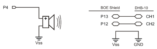
The diagram below shows where to connect each 3-wire Ping))) sensor cable. If you’re looking at the color version, note that each black wire is connected to either GND on the breadboard, or the GND terminal in the servo header (labeled Black to the right of the header block). Each of those black wires should also be connected to a Ping))) sensor’s GND pin.
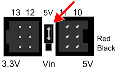
IMPORTANT: The power jumper between BOE Shield servo ports 11 and 12 should also be set to 5V.
WARNING: Wiring errors can damage the Ping))) sensors and/or your Arduino. Do not turn power back on until you have double-checked all the connections in this section’s checklist below.


The Terminal display after connecting the Ping))) sensors and running the example sketch will resemble this. If all the Ping))) sensors are connected correctly, the display should show the centimeter distances of obstacles placed in front of each one (within its 3 cm to 3 m range, and typically good to +/- 1 cm).
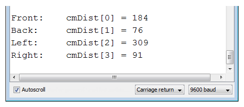
In the terminal, the right left Ping))) sensor does not see an obstacle, either because it’s beyond the 3 m limit, or the obstacle might be at an angle that’s reflecting the ultrasonic energy away from (instead of back to) the sensor. If you put your hand about 10 cm in front of the right sensor, that value should change to about 10. Make sure that each sensor correctly reports distances when you do that.
/*
  Arlo-Test-Ping-Sensors
*/

String directions[4] = {"Front:    ",         // Directions for display
                        "Back:     ",
                        "Left:     ",
                        "Right:    "};
int pingPin[4] = {11, 10, 9, 8};              // Ping pins
int cmDist[4];                                // Cm distances
int i = 0;                                    // Index, stat at 0

void setup()                                  // Setup function
{
  Serial.begin(9600);                         // Start terminal communication
}

void loop()                                   // Main loop
{
  cmDist[i] = pingCm(pingPin[i]);             // Get distance

  Serial.print(directions[i]);                // Display direction
  Serial.print("cmDist[");                    // Display variable name
  Serial.print(i);                            // Display variable index
  Serial.print("] = ");                       // Display ] & =
  Serial.println(cmDist[i]);                  // Display value
  i++;                                        // Increase index by 1
  if(i == 4)                                  // If index is 4
  {
    i = 0;                                    // Reset index to 0
    delay(1000);                              // Wait a second
    Serial.println();                         // Print a blank line
  }
}

int pingCm(int pin)                           // Ping measurement function
{
  digitalWrite(pin, LOW);                     // Pin to output-low
  pinMode(pin, OUTPUT);
  delayMicroseconds(200);                     // Required between successive
  digitalWrite(pin, HIGH);                    // Send high pulse
  delayMicroseconds(5);                       // Must be at least 2 us
  digitalWrite(pin, LOW);                     // End pulse to start ping
  pinMode(pin, INPUT);                        // Change to input
  long microseconds = pulseIn(pin, HIGH);     // Wait for echo to reflect
  return microseconds / 29 / 2;               // Convert us echo to cm
}
Integration and deadzone are part of a group of values that may need to be tuned to accommodate certain payload weights, gearbox play, and to optimize performance at certain speeds.
If your battery is charged, and the payload is small, the default settings should be fine. If payloads increase and decrease during runtime, you may wish to programmatically adjust those constants, either to give it some extra push to get to each final goal, or to apply less push toward the final goal to prevent oscillations (repeated over corrections).
The next example sketch adjusts two of those constants, named KI and DZ. Thier values can be read from the DHB-10 with the ArloRobot readConfig function, and pass “KI” to read the KI constant, DZ to read the DZ constant. For example, Arlo.readConfig(“KI”) returns the DHB-10 motor controller’s current KI value. To modify those values, use the ArloRobot writeConfig function. For example Arlo.writeConfig(“KI”, 65) sets the value of KI to 65.
Arlo.storeConfig calls for making the changes semi-permanent by writing them to the DHB-10’s EEPROM have been commented out. For example, Arlo.storeConfig(“KI”) would make whatever value has been most recently loaded into the DHB-10 the default when it starts up. So, long as you keep the lines with STORE commented, the changes only affect performance until the DHB-10 is restarted. You can restart the DHB-10 by pressing and releasing its Reset button or turning the Motors power off, and then back on.
NOTE: For more information, see the DHB-10 command set in the DHB-10 Motor Controller Firmware Guide [6].
/*
  Arlo-Tune-Integral-Constants

  Set control system constants that give the extra push to get to the
  final position and control the allowable positional error.
*/

#include <ArloRobot.h>                        // Include Arlo library
#include <SoftwareSerial.h>                   // Include SoftwareSerial library

// Arlo and serial objects required
ArloRobot Arlo;                               // Arlo object
SoftwareSerial ArloSerial(12, 13);            // Serial in I/O 12, out I/O 13

void setup()                                  // Setup function
{
  tone(4, 3000, 2000);                        // Piezospeaker beep
  Serial.begin(9600);                         // Start terminal serial port

  ArloSerial.begin(19200);                    // Start DHB-10 serial com
  Arlo.begin(ArloSerial);                     // Pass to Arlo object

  int ki = Arlo.readConfig("KI");             // Check KI
  Serial.print("KI = ");                      // Display KI
  Serial.println(ki);

  int dz = Arlo.readConfig("DZ");             // Check DZ
  Serial.print("DZ = ");                      // Display DZ
  Serial.println(dz);

  Arlo.writeConfig("KI", 65);                 // Change KI
  Arlo.writeConfig("DZ", 1);                  // Change DZ

  // Uncomment code below to store new settings to the DHB-10's EEPROM.
  // Tip: To uncomment, replace the two * characters with / characters.

  /*
  Arlo.storeConfig("KI");                    // New KI to DHB-10 EEPROM
  Serial.println(Arlo.lastExchange);

  Arlo.storeConfig("DZ");                    // New DZ to DHB-10 EEPROM
  Serial.println(Arlo.lastExchange);
  */
}

void loop() {}                                // Nothing for main loop
Important: Keep Your DHB-10 Firmware Up-to-Date!
The DHB-10 firmware is expected to undergo occasional revision as continual improvements are made by Parallax and by the community. It is important to make sure your firmware is up to date.
To make sure you always have the latest firmware version, bookmark the following pages and check back regularly for updates: Updating Your Firmware [7], DHB-10 Firmware Download Page [8]
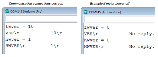
If the Arlo replies with 0 values for fwver and hwver, this sketch will display the entire transaction between Arduino and DHB-10. The lines with the \r shows the actual serial communication from Arduino to DHB-10 (VER\r) and from the DHB-10 to the Arlo (10\r if communication, or messages like No reply in the case where the motor power is not on).
/*
  Arlo-Troubleshoot-Arduino-DHB-10-Communication

  http://learn.parallax.com/tutorials/robot/arlo/arlo-basic-stamp-boe-bot-brain/

  You'll re ready for the next step when the Arduino Terminal displays:

  fwver = 10
  hwver = 1
*/

#include <ArloRobot.h>                        // Include Arlo library
#include <SoftwareSerial.h>                   // Include SoftwareSerial library

ArloRobot Arlo;                               // Declare Arlo object
SoftwareSerial ArloSerial(12, 13);            // Declare SoftwareSerial object
                                              // DHB-10 -> I/O 12, DHB-10 <- I/O 13
void setup()                                  // Setup function
{
  tone(4, 3000, 2000);                        // Piezospeaker beep
  Serial.begin(9600);                         // Start terminal serial port

  ArloSerial.begin(19200);                    // Start DHB-10 serial communication
  Arlo.begin(ArloSerial);                     // Pass to Arlo object

  int fwver = Arlo.readFirmwareVer();         // Check DHB-10 firmware
  Serial.print("fwver = ");                   // Display firmware version
  Serial.println(fwver, DEC);
  Serial.println(Arlo.lastExchange);

  int hwver = Arlo.readHardwareVer();         // Check DHB-10 hardware
  Serial.print("hwver = ");                   // Display hardware version
  Serial.println(hwver, DEC);
  Serial.println(Arlo.lastExchange);
}

void loop() {}                                // Nothing for main loop

Links
[1] http://learn.parallax.com/tutorials/robot/arlo/arlo-robot-assembly-guide
[2] https://codebender.cc/
[3] https://www.arduino.cc/en/Main/Software
[4] http://learn.parallax.com/support/download/1352/arlo-boe-shield-arduino-library-example-code
[5] http://learn.parallax.com/tutorials/robot/arlo/arlo-arduino-uno-boe-shield-brain/troubleshooting-your-arlo-boe-shield
[6] https://www.parallax.com/downloads/dhb-10-motor-controller-firmware-guide
[7] http://learn.parallax.com/tutorials/robot/arlo/updating-your-dhb-10-firmware
[8] https://www.parallax.com/downloads/dhb-10-motor-controller-firmware
[9] http://learn.parallax.com/tutorials/robot/arlo/arlo-robot-assembly-guide/section-8-arlo-top-deck