Let's run an number of tests to make sure the electrical connections are correct before trying to run the Arlo, starting with the battery.
IMPORTANT: If you have not already done so, make sure your batteries are freshly charged. Follow the instructions on the charger case. Batteries should be recharged to 12.6 V before they discharge below 12 V.
Let’s make sure to clear the sketch in the Arduino before turning Motors power on. That way, some BOE Shield-Bot sketch that used to be in there won’t send your Arlo into unexpected maneuvers.
/*
Arlo-No-Surprise-Maneuvers.ino
Run this before ever turning on power to the Arlo's motors to prevent any
unexpected motions.
*/

void setup()                                   // Setup function
{
 tone(4, 3000, 2000);                          // Piezospeaker beep
 Serial.begin(9600);                           // Start terminal serial port
 Serial.print("Your Arlo will stay still.");   // Message
}

void loop() {}                                  // Nothing for main loop
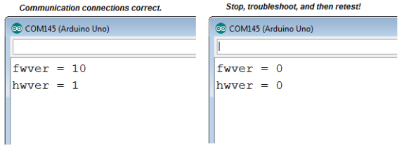
This next sketch asks the DHB-10 for its hardware and firmware versions, and displays the results in Terminal. Here is what you’ll see if your Arduino communicates successfully with the DHB-10 (left) alongside messages you might see if communication fails (right).
IMPORTANT: Your Arlo will not be ready for the next step until it displays nonzero values for fwver and hwver.
NOTE: If your terminal output resembles the one on the right, try the Arlo Failed the Communication Test section in Troubleshooting [1].
/*
Arlo-Test-Arduino-DHB-10-Communication
You'll be ready for the next step when the Arduino Terminal displays:
fwver = 10
hwver = 1
*/

#include <ArloRobot.h>                     // Include Arlo library
#include <SoftwareSerial.h>                   // Include SoftwareSerial library

ArloRobot Arlo;                            // Declare Arlo object

SoftwareSerial ArloSerial(12, 13);            // Declare SoftwareSerial object
                                              // DHB-10 -> I/O 12, DHB-10 <- I/O 13
void setup()                                  // Setup function

{
 tone(4, 3000, 2000);                        // Piezospeaker beep
 Serial.begin(9600);                         // Start terminal serial port

 ArloSerial.begin(19200);                    // Start DHB-10 serial communication
 Arlo.begin(ArloSerial);                     // Pass to Arlo object

 int fwver = Arlo.readFirmwareVer();         // Check DHB-10 firmware
 Serial.print("fwver = ");                   // Display firmware version
 Serial.println(fwver, DEC);

 int hwver = Arlo.readHardwareVer();         // Check DHB-10 hardware
 Serial.print("hwver = ");                   // Display hardware version
 Serial.println(hwver, DEC);
}

void loop() {}                                // Nothing for main loop
This next sketch sets the Arlo’s motors to 20/127 of full power in the forward direction. If your Arlo goes forward while running this sketch, it indicates that your motors are connected correctly and the battery is charged.
IMPORTANT: Your Arlo will not be ready for the next step until it goes forward for this test.
/*
Arlo-Test-Motor-Connections
Run this sketch to verify that your Arlo goes forward.
*/

#include <ArloRobot.h>                       // Include Arlo library
#include <SoftwareSerial.h>                  // Include SoftwareSerial library

ArloRobot Arlo;                              // Declare Arlo object
SoftwareSerial ArloSerial(12, 13);           // Declare SoftwareSerial object

                                             // DHB-10 -> I/O 12, DHB-10 <- I/O 13

void setup()                                 // Setup function

{
 tone(4, 3000, 2000);                        // Piezospeaker beep
 Serial.begin(9600);                         // Start terminal serial port

 ArloSerial.begin(19200);                    // Start DHB-10 serial communication
 Arlo.begin(ArloSerial);                     // Pass to Arlo object

 Arlo.writeMotorPower(20, 20);               // Go forward very slowly
 delay(3000);                                //   for three seconds
 Arlo.writeMotorPower(0, 0);                 //   then stop
}

void loop() {}                                // Nothing for main loop
The Arlo has built-in encoders that can count how far the Arlo travels in terms of 144ths of a wheel revolution. Although it’s not needed to run BOE Shield-Bot code, it’s best to make sure they are functioning correctly in case you want to improve the accuracy of the Arlo’s maneuvers later. The next sketch will display the status of your encoder connections in the Terminal. If there is a problem, it may indicate that the encoder cables have been swapped or that there is some other wiring problem. Here are examples of what you might see:

/*
Arlo-Test-Encoder-Connections

This sketch tests to make sure the Arlo's wheel encoder connections
are correct.  The Arlo will not be ready for the next step until you
have verified that the number of encoder transitions (ticks) for both
wheels are positive when the wheels roll forward.

If you have not already completed Test Arlo Motor Connections.c,
complete it first, then continue from here.

Use the Arduino IDE’s Upload button to run this sketch.  If the
Terminal displays the "Encoder connections are correct!..."
message, your Arlo is ready for the next step, which is running
navigation sketches.

If the Terminal instead displays one or more "ERROR..."
messages, those encoder encoder connections will need to be
corrected.  For example, if the messages says, "ERROR: Motor 1
encoder connections are reversed!", you will need to unplug and
swap the two 3-wire encoder cables next to the Motor 1 terminal
on the DHB-10, swap them, and plug them back in.

Make sure to test between each adjustment.  Your arlo will not be
ready for the next step until you get the success message from
this test.
*/

#include <ArloRobot.h>                     // Include Arlo library
#include <SoftwareSerial.h>                   // Include SoftwareSerial library

// Arlo and serial objects required
ArloRobot Arlo;                            // Arlo object
SoftwareSerial ArloSerial(12, 13);            // Serial in I/O 12, out I/O 13

int countsLeft, countsRight;                  // Encoder counting variables
void setup()                                  // Setup function
{
tone(4, 3000, 2000);                        // Piezospeaker beep
Serial.begin(9600);                         // Start terminal serial port

 ArloSerial.begin(19200);                    // Start DHB-10 serial com
Arlo.begin(ArloSerial);                     // Pass to Arlo object

 Serial.println("Testing...");               // Display testing message

 Arlo.clearCounts();                         // Clear encoder counts

 Arlo.writeMotorPower(32, 32);               // Go forward very slowly
delay(4000);                                //   for three seconds
Arlo.writeMotorPower(0, 0);                 //   then stop

 countsLeft = Arlo.readCountsLeft();         // Get left & right encoder counts
countsRight = Arlo.readCountsRight();

 Serial.print("countsLeft = ");              // Display encoder measurements
Serial.print(countsLeft, DEC);
Serial.print(", countsRight = ");
Serial.println(countsRight, DEC);
Serial.println();

 // Both distances positive?
if((countsLeft > 175) && (countsLeft < 325)
&& (countsRight > 175) && (countsRight < 325))
{
   // Success message
   Serial.println("Encoder connections are correct!");
   Serial.println("Your Arlo is ready for the next step.");
   Serial.println();
}
else
{
   // Left encoders cables correct?
   if(countsLeft > 175 && countsLeft < 325)
   {
     // Correct encoder message
     Serial.println("Motor 1 encoder cables are connected");
     Serial.println(" correctly.");
     Serial.println();
   }
   // Left encoders cables swapped?
   else if(countsLeft > -325 && countsLeft < -125)
   {
     // Swapped encoder message
     Serial.println("ERROR: Motor 1 encoder connections");
     Serial.println(" are reversed!");
     Serial.println();
   }
   else                                      // Other problem
   {
     // Other encoder error message
     Serial.println("ERROR: Motor 1 encoder values out of ");
     Serial.println("range. Recheck encoder connections ");
     Serial.println("and assemblies.");
     Serial.println();
   }
   // Right encoders cables correct?
   if(countsRight > 175 && countsRight < 325)
   {
     // Correct encoder message
     Serial.println("Motor 2 encoder cables are ");
     Serial.println("connected correctly.");
     Serial.println();
   }
   // Right encoders cables swapped?
   else if(countsRight > -325 && countsRight < -125)
   {
     // Swapped encoder message
     Serial.println("ERROR: Motor 2 encoder connections ");
     Serial.println("are reversed!");
     Serial.println();
   }
   else                                      // Other problem
   {
     // Other encoder error message
     Serial.println("ERROR: Motor 2 encoder values ");
     Serial.println("out of range. Recheck encoder ");
     Serial.println("connections and assemblies.");
     Serial.println();
   }
}

 Arlo.writePulseMode();                      // Get ready for pulse control

 Serial.print("Test done.\n\n");             // Display status
}


void loop() {}                                // Nothing for main loop

Links
[1] http://learn.parallax.com/tutorials/robot/arlo/arlo-arduino-uno-boe-shield-brain/troubleshooting-your-arlo-boe-shield