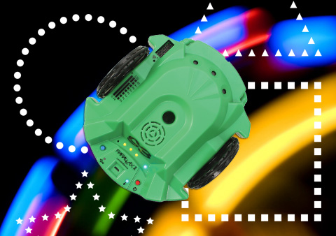
Now that you are familiar with BlocklyProp and have experimented with your Scribbler 3 robot's LEDs, let's get driving!
In Simple Motion for Motor Blocks, the tutorials here will introduce you to the blocks that make your S3 robot move. There are several different ways to program your robot so it can drive. We will start out simple, and then work our way into more complex blocks that give you more control over your robot's motion.
Before you begin, you should have already completed:
If you are ready to proceed, click the following links and let the fun begin!
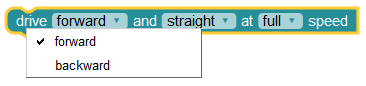
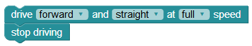
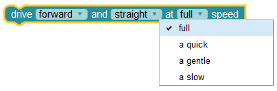
It's been fun up to this point, but I bet you're ready to see the S3 move! The simplest way to get your S3 rolling is by using the drive block. It is located under the ACTIONS > MOTORS category and looks like this:

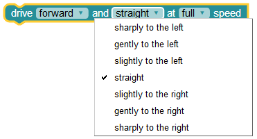
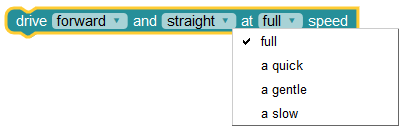
In this one block, you can control many important aspects of the S3’s movement using each of its three drop-down menus - forward, straight, and full in the image above. By clicking on each menu, the various options appear allowing you to select the one you need.
The first menu allows you to set drive direction: forward or backward.
The second menu lets you choose to travel straight or in a curved path - turning slightly to the left or right, gently to the left or right, or sharply to the left or right.
The third menu allows you select the speed at which you want your S3 to move full (100%), quick (75%), gentle (50%), or slow (25%). These speeds are based on an approximate percentage of S3’s maximum speed, which can differ based on the slope and texture of your driving surface.
Give it a try!
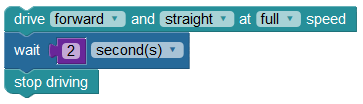
Do you see a problem? Your S3 continues to move forward and straight at full speed with no end in sight. You need a way to stop!
The S3 robot uses a differential drive system. This means that there are two drive wheels, each with its own motor, allowing them to move independently at different speeds and directions. On the S3 robot the drive wheels are located on the midline of the robot’s chassis and there is an unpowered tail wheel at rear. As you progress through these tutorials, you will come to appreciate this highly maneuverable design.
Understanding these concepts will help you program your S3's movement properly. If this is difficult to visualize in your head, try drawing it out on paper. Use arrows to show which direction each wheel will go in each of the 3 situations we listed here.
You will find the stop driving block under the same categories where you found the drive block.
Your S3 stopped, because it didn’t drive anywhere, correct? This is because just milliseconds after the S3 received its drive command, it was given the stop driving command. To make the robot do what you want, you still need one more block - the wait block.
The wait block can be found in the CONTROL category:

The default unit of this block is in millisecond(s). Value can be set by changing the number in the inner purple value block.
It works! Now let’s try something new.
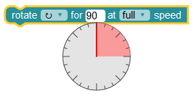
To do this in another way, let’s learn about one more block - the rotate block. You will find it in the ACTIONS > MOTORS category. It looks like this:

The rotate block has settings for the spin direction (clockwise or counterclockwise - sometimes called anti-clockwise), the number of degrees to turn, and the speed of rotation (full, a quick, a gentle, or a slow speed). The degrees to turn menu drops down a neat tool allowing you to easily set your desired degrees (or you can type in any number between 1 and 359). See below where it has been set to 90 degrees:
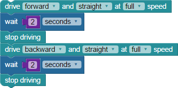
Now, try this by writing a program that drives forward and back with a bit more style. You should have something that looks like this:

In the program above, as the robot reaches the rotate block, the S3 stops so quickly from full speed that you will hear the tail wheel chatter up and down.
What did you change? Did it work? Try different ideas until that chatter disappears. What did you learn?
Special thanks to Parallax friend Whit Stodghill for his assistance in writing, editing, and testing material for these S3 tutorials.
Now that you've tried basic driving with the S3 robot, you will be ready to move on to slightly more complex motion commands. Start by taking a look under the ACTIONS > MOTORS block category, locating the drive speed block.
Take a close look at the two large wheels on the left and right side of the robot. Each of these is attached to a gear motor inside the plastic case. The rear tail wheel is not powered, but it does monitor whether the S3 is moving or stalled (more about that later).
The drive speed block has three parameters (values) you may enter:
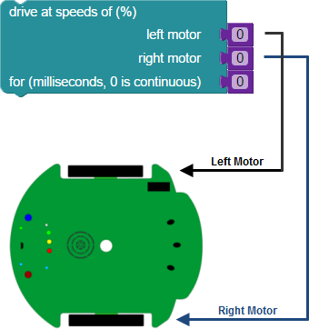
Setting the right motor speed and left motor speed for the same value over a certain duration would cause the S3 to travel forward or backward in a straight line. Small changes in direction might occur on a tile floor or carpet because of friction, small obstructions, uneven, or sloped surfaces encountered along the way. Variations like these, or wheel slippage could keep us from arriving perfectly at our intended destination.
When studying the physics of motion, you often learn that there can be some variation between theory and real world conditions. An example of this idea is that you might ignore the effects of friction or air resistance when doing theoretical calculations, yet when you start looking at real-world examples, these forces remain present and cannot be ignored.
Your S3 robot operates in the real world, therefore you will encounter variation in the way it moves at different speeds and on different surfaces. This is due in part to the way the S3’s motors respond at various speeds, changes in current, internal resistance, friction - even changes in the gear lubrication over time. As noted above, different sloped or irregular drive surfaces may also cause changes in observed movement.
Put plainly, this means that there will be noticeable differences in your S3's motion as you drive at different speeds and on different surfaces. Do not mistake these variations for limitations. The S3 is quite capable of moving very exact distances and directions. This does mean that some ways of controlling the S3’s movement are more accurate than others, as you will discover in future tutorials.
Let’s look at an example.
You are probably familiar with the equation d = rt, which shows that the distance your robot travels is a function of how fast it is moving and for how long. While you can use a variety of units in this equation we’ll keep it simple was below:
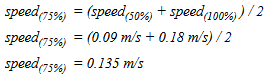
At 100% drive speed the S3 moves about 0.18 m/s, and at 50% drive speed around 0.09 m/s or about half as fast. An S3 moving at 100% speed for five seconds should travel exactly twice the distance of an S3 moving at 50% speed for five seconds.
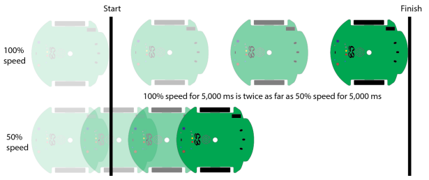
The following two blocks both result in the S3 arriving at the same destination – just at different times. This is theoretically what should happen... but we operate in the real real world. Differences in how the motors respond, variations in driving surface, or other conditions that cause friction or slippage make this approximately true.
Putting these values in the d = rt formula as below demonstrates this idea.
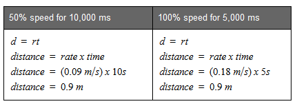
According to this equation, an S3 programed with a drive speed value of 50% can travel the same distance as an S3 with a 100% drive speed value, simply set the duration for twice as long. Further along in this tutorial, you will experiment with this process and you will be able to observe the real world variations that can occur.
Some food for thought as you experiment with navigation programs: a slower moving robot is often more precise and easier to control than a fast moving one since it has less abrupt changes in speed.
The Mars Science Lab, MSL - Curiosity Rover [3] is in its 5th year of exploration on Mars. Based on variables including power levels, terrain difficulty, slippage, and visibility, the maximum terrain-traverse speed is estimated to be 200 m (660 ft) per day using automatic navigation. It can travel up to 90 meters (300 ft) per hour but the average speed is 30 meters (98 ft) per hour. Source: https://en.wikipedia.org/wiki/Curiosity_(rover)
Remember that the S3 travels 0.18 meters per second at top speed, or 10.8 meters per minute - which is a speed of 648 meters (or 2,125 feet) per hour! Our S3 moving at a controlled speed can cover in 1 hour what the Mars Science Lab covers in 1 day.
To be fair to the Curiosity Rover though, the surface of Mars is more difficult terrain than our home or classroom floor or tabletop. Of course, Curiosity doesn’t have a pen port for a Sharpie® either!
The drive speed block can be used in two different ways: with or without a duration value. When a duration value greater than zero is used it's considered a blocking command. This is because the S3 does not proceed to the next line of code until the duration value has elapsed.
When a duration is not set (that is, left at the default of zero), the motor direction and speed are maintained forever or until changed by another block. This is referred to as a non-blocking command.
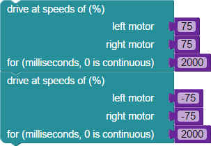
This program takes about four seconds (4000 ms) to run. The S3 moves forward at 3/4 speed (75%), stops, and returns to where it started (there and back again).
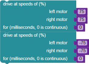
This program makes the S3 robot move backwards, forever. Notice that there is actually a forward motion block first. Because it has no set duration, it is changed instantly by the second block (backward motion). Since there is nothing after it, the backward motion block runs forever.
Why would you use a time blocked drive speed command instead of a non-blocked drive speed command? Time blocking commands are useful for drawing more accurate shapes with a Sharpie® in the S3’s pen port, and for other activtities requiring the S3 to travel a precise distance. Distance commands will be discussed in later tutorials.
You will learn as you continue to work with your S3 which movement control methods work best and most accurately in certain conditions. Non-blocked driving commands are more useful for sensor-based navigation, where the S3 must respond immediately to changes in the physical environment. Examples: light-following, line-following, or object detection and avoidance with infrared sensors.
A single program can usually be developed several different ways and have the same, or similar, end results. Within the CONTROL menu the wait block can be used with a non-blocked drive speed block and have the same result as a drive speed block with a time duration. For example, these two programs produce the same result:

You may have noticed the third drive speed block on the program on the right. This block is necessary in order to tell your robot to stop. In an earlier tutorial you learned that the wait block means pause, but it's a bit more complicated than that. Picture a light. When you slip the light switch on, the light turns on. And while it waits for the next command, it continues to follow the previous ON command. Then you flip the switch off, and the light turns off. Again it waits for the next command, continueing to follow the OFF command. All while the motor itself is still running. The third drive speed block is in place and set to zero in order to stop the motor entirely.
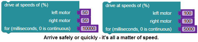
Program the S3 to drive forward at 100% speed for 4000 ms and then drive backwards to the starting point at 50% speed. Make a tape square around your S3 to test your program to be sure you returned to the starting point.
Here is an example:
How did your S3 perform? Did it return to the exact spot where it began? What factors did you have to modify to make your S3 return to the exact spot? Remember that however you have to vary your settings to have the S3 drive forward and backward to the exact point, the formula above applies. Distance (d) = rate (r) x time (t). Using exactly ½ speed (100% and 50%), how close does your time come to being double? Using exactly double the time (4000 ms and 8000 ms), in what way does your speed setting have to change to start and end at exactly the same spot?
Engineers, programmers, and roboticists often keep notebooks (digital or paper) of experiments and/or the results of tests, designs, or methods of doing something as they work. For example, many electronics hobbyists know of Forrest M. Mims III [4]’s wonderful Notebook [5] series.
It is a great idea and helps you remember what you’ve done, what worked, and what did not. Try to get into this habit in your own work.
It is always true that distance (d) = rate (r) x time (t) when given perfect conditions with no friction or other challenges. Since our conditions are not perfect, let's record your results for the Try This example shown above in a chart like the one below. This should give you an idea of how the ideal varies from your actual real world results.
Try This Results - Drive Forward 4000 ms at 100% and return to start point at 50% speed.
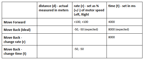
The S3s drive speed settings, 0 to 100% (+ for forward movement and - for reverse movement), have some real world limitations. The relationship between 25%, 50%, 75%, and 100% drive speeds are not exactly proportional in the real world. There is, of course, a speed setting (based on specific conditions) that is exactly half of the speed setting of 100%. The percentage settings in the drive speed block are good approximations, but they are approximations. This means that if you need the S3 to drive at half-speed, you will likely have to test a few different speed settings in order to get it right for your environment.
Note: Remember, as stated above, that there are more accurate ways to control the S3’s movement and that these methods will be covered in other tutorials.
For now, let’s continue to experiment...
Special thanks to Parallax friend Whit Stodghill for his assistance in writing, editing, and testing material for these S3 tutorials.
The S3 robot has internal encoder sensors and pre-programmed logic to keep the robot going exactly where you programmed it to go. Without encoders, it would be difficult to make the S3 travel in a straight line as pairs of motors are never precisely matched on their own.
Encoder sensors monitor encoder ticks (explained further, below, in Did You Know?) that the S3 uses to adjust left and right motor speeds as it performs maneuvers. These sensors are what allow the robot to precisely match the speed and/or distances as defined in your program. If the surface you are working on is smooth, such as a desktop, encoders will enable the S3 to return to the programmed starting point and do precise dead reckoning navigation.
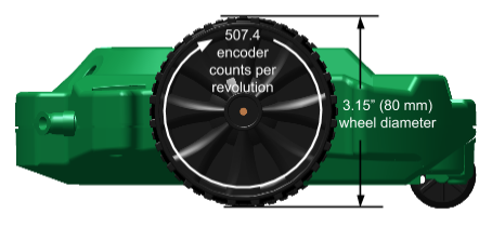
Encoders provide a closed loop control system where the drive speed may be controlled and measured continually during operation. The S3’s motors have a gearbox on one side and an optical encoder on the other. The optical encoder has four slots which are counted by a change of state in an infrared slot sensor. With the gear reduction, a full rotation of the wheel has 507.4 encoder transitions or encoder ticks. The S3 robot’s internal encoders are mounted on the printed circuit board (PCB), connected to the motor shaft. If you'd like, you can carefully open up your S3 and take a look – but be sure to save all hardware you remove so you can properly seal the shell when you are done.
 /
/

The S3 has 507.4 encoder counts per complete wheel revolution (0.491 mm / count). The diameter of the wheel is 3.15” (80 mm).
Circumference = pi * diameter (C = π d)
To determine how far the S3 travels when the wheel turns one complete rotation you could use the following formula to determine the circumference of the wheel:
C = π d
In this equation “C” represents the circumference of the wheel and “d” is its diameter. The number π is the mathematical constant pi, commonly approximated to 3.14159. Using only two significant digits, one which was obtained by measuring the wheel, C is equal to (in imperial and metric):
C = (3.14)(3.15 in)
C = 9.89 in
or
C = (3.14)(80 mm)
C = 251.2 mm
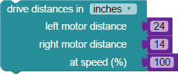
The drive distance block lets you program the S3 to move an exact distance.

Remember: Your S3's speed is affected by the slope and material of the surface it is driving on. Refer back to the previous tutorial if you need a reminder about the effect of real world limitations on motion calculations.
The drive distance block is a time blocked command. The S3 must finish this command before continuing on to other blocks. Similar to using the drive speed block, the time required to reach your destination is a function of the speed you choose.
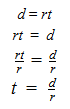
time (t ) = distance (d) / rate (r)
How long does it take to travel a certain distance? You are familiar with the equation d = rt from the prior tutorial where you used the drive speed block with rate and time, solving for distance (d). In this example, you have distance (d) and rate (r) and can solve the same equation for time (t).
An S3 robot moving a distance (d) of 100 cm at 100% speed (r) should take approximately twice as long (t) as an S3 moving 100 cm at 50% speed.

Putting these values in the t = d/r formula we derived above demonstrates this point.
Going half the speed takes about twice as long as full speed, but you wind up at exactly the same place.
Your blocks might look like this:

total time = t(first drive distance block) + t(second drive distance block)
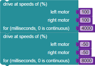
For the first drive distance block the S3 moves 1 m at 100% speed:
time = distance / rate time
time = (1 m) / (0.18 m/s)
time = 5.56 s
For the second drive distance block the S3 moves 1 m at 50% speed:
time = distance / rate time
time = (1 m) / (0.09 m/s)
time = 11.11 s
total time = 5.56 s + 11.11 s = 16.67 s
Hint: 100% speed is 0.18 m/s and 50% speed is 0.09 m/s. 75% speed is approximately halfway between 50% and 100%.
Hint: You will also need to calculate the speed(25%) which is halfway between speed(0%) and speed(50%).
Hint: Re-read the "Did You Know?" section above for an explanation of encoder counts/ticks.
Special thanks to Parallax friend Whit Stodghill for his assistance in writing, editing, and testing material for these S3 tutorials.
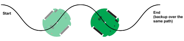
There are definite benefits to using a robot with a rounded chassis and close-fitting wheels. Round robots have excellent drivability; if your S3 hits a chair leg or wall it can rotate in place to find an escape route. A square-shaped robot can catch its corners on obstacles where a round robot would not. Further, robots with a symmetrical drive configuration located at their center line have the ability to make zero-turn radius (ZTR) maneuvers. Because the S3 can scribble or draw with a Sharpie® pen placed in its pen port (or with certain dry-erase markers for use on white boards) both of these features are particularly important.
Let’s take a look at the various turn options for the S3.
A ZTR turn requires the two drive wheels to move in opposite directions at the same speed for the same duration of time. This type of turn causes the S3 to pivot in place in a clockwise or counterclockwise direction. Speed and time combine to control the amount of rotation. We will demonstrate this when we discuss the rotate and drive a turn blocks later in the tutorial.

Locking one wheel in place and driving the other in either direction is a one-wheel turn. These turns make a tight outer radius equal to twice the diameter of the S3 robot. To make a turn at a tighter radius both drive wheels are used with the second wheel rotating the opposite direction at a different speed (remember, equal speed in the opposite direction equals a zero-turn radius). Different wheel speeds and duration combine to control the rotation amount and size of radius. One-wheel turns are best made with the drive speed block covered previously in Drive There and Back Again [6].

Driving both wheels forward (or both backward) at different speeds creates a wide-radius turn. The S3 moves along a wide arc as it moves forward or backward. Speed and time values combine to control the radius and the length of the arc. You can play around with adjusting these values to change your robot's behavior.

The S3 is the third edition of a very successful run of Scribbler robots that started with the original blue colored Scribbler Robot (shown in the robot comparison image from the Setting Up BlocklyProp for the S3 [7] tutorial). The original blue Scribbler did not have any wheel encoders (used to accurately measure wheel movement) and it used a single-core processor called the BASIC Stamp 2. The BASIC Stamp 2 is only capable of doing one thing at a time, so it was unable to drive the wheels and monitor encoders simultaneously. The S3 robot uses the Propeller multicore microcontroller, which is capable of handling multiple simultaneous operations.
The limited capability of the single-core processor in the original Scribbler Robot made it a challenge to drive in an accurate straight line or curved path.
The drive block can be found in the ACTIONS > MOTORS category. As you learned in the Driving Basics [8] tutorial, you can control the direction of travel, path of travel, and speed. This is a non-blocking command because it runs continuously until it is changed.
Direction of travel is either forward or backward.

The directional drop down choices on the drive block adjust the approximate direction of one or both wheels in the following manner:
The speed drop down choices set the approximate overall speed (for straight travel) or the speed of the the outside wheel (in a right or left turn, or arc).
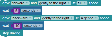
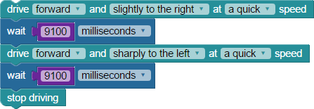
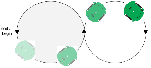
Let’s take a quick look at an example program that makes the S3 drive forward and gently to the right at full speed, then backward and gently to the right at a gentle speed to about where it started (because speed is not actually linear, there may be some difference in distance traveled in each direction).
Using the drive block to drive a specific distance is a function of time (given in the wait block) and speed. Precise, encoder-based movements are only available in more advanced blocks like drive speed and drive distance.
The rotate block (located in the ACTIONS>MOTORS category) controls zero-turn radius (ZTR) turns. This block combines drop down menus for direction (clockwise or counterclockwise), with degrees to rotate (or any number between 1 and 359 may also be entered manually), and speed. The rotate block is very useful for the type of dead-reckoning precision movements used in artwork, maze-solving, and return-to-home challenges. This block is a time-blocking command (it runs until it’s finished, and then the S3 stops):

The ACTIONS > MOTORS category contains blocks that allow you to input precise travel distances for each wheel. The following drive distance block can be particularly useful for sensor-based navigation where you want the robot to perform a turn in response to an input (light level, object detected) in a repeatable manner. For example, sensing surrounding light levels, and then turning a particular distance based on the amount of light detected. You may have seen your robot do this already if you tried running its default demo program #2.
The ACTIONS > MOTORS menu drive a turn block is for moving the S3 through a turn with number of degrees, radius value, and top speed set by the user. This block can do zero-turn radius and arc turns depending on your radius value (leave at 0 for a ZRT turn, put in a value greater than 0 for an arc).
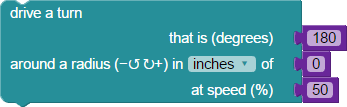
The drive a turn block could be used as part of a navigation program that takes and saves distance measurements with a PING))) sensor mounted on the robot at 0, 90, and 180 degree positions. This would allow the S3 to find the most open area to navigate towards as it roams. As you will learn in future tutorials, the infrared sensors built into your robot detect the presence of an object up to 18” away, but do not actually provide feedback on how far the obstacle actually is. A PING))) can sense an obstacle (ultrasonically) and provide a distance measurement of its location up to to 100 cm away.

Special thanks to Parallax friend Whit Stodghill for his assistance in writing, editing, and testing material for these S3 tutorials.
We know that the S3 can be a very maneuverable robot. The robot’s shape, drive wheel location, and configuration give programmers the ability to finely control its movement. Since we have just finished covering turns and arcs, let’s put your new understanding to the test by programming your robot to create some simple shapes.
If you tried out your demo programs, you will recall that demonstration program #7 scribbled a figure eight, paused, and then made a path in the shape of a square. We will show you how to create the square and figure eight programs in BlocklyProp, and adding some additional challenges along the way.

You have used the drive, wait, rotate, and stop driving blocks already. For these, and any other previously used blocks, we will no longer be adding instructions on where to find them in the BlocklyProp workspace. If you cannot remember where to find them, look around! That’s the best way to learn where everything is.
How did work? If there was a problem, check your blocks. You will notice that after the last side of the square is run, the robot turns. This 90° turn is not required to “close” the square, but it will return the S3 to its original place and orientation.
There is an old expression that experienced programmers use: “Work hard at being lazy!” This means that our code should always try to accomplish as much as possible, in as little code (or blocks) as possible. So, how might you make the code you created above better and more efficient? This program drives forward for 2 seconds and turns 90° - 4 times. That repetition should get you thinking about loops. Remember that program loops allow you to do a process repeatedly, without writing the command again and again. Edit your code by adding one block and deleting nine:
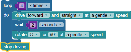
You should have added the loop (x times) block and deleted 3 drive, 3 wait, and 3 rotate blocks. Working hard to be lazy – reducing program space resulted in simpler and more elegant code.
The programming language running these blocks is C. Even without knowing how to read or write in C, you can easily see the effect that this optimizing has on your program's size and complexity.
Geometry is a branch of mathematics concerned with the properties and relations of points, lines, surfaces, and solids. Geometry helps us describe and measure basic shapes - squares, triangles and circles. Each is created by combining lines and/or curves.
Shapes are formed by describing the relationship between the components that form the shape, not with fixed dimensions or size. A square is a square, regardless of its size. Similarly, a computer program defines the relationship between the steps or pieces of a process. A program describes a process by relationships. It is a code for how to do something - a pattern.
The exact same blocks you have been using, but with slightly different parameters, can create a triangle.

To make this triangle program you changed one setting: the rotation angle changed to 120° (this will form a 60° angle inside our triangle). Note that you repeated your code for only three sides instead of four. The last rotation gets your S3 back to its starting point. It doesn’t take much work or imagination at all to see how this can be simplified. Just like before, you will add one block and delete many.
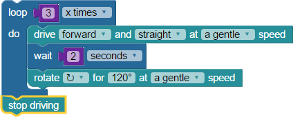
The loop (x times) block repeats the drive, wait, and rotate blocks 3 times, finishing again with the stop driving block.
Did you ever notice that a figure eight turned sideways is the symbol for infinity: 8 or ∞. As promised, let’s drive a figure 8 pattern or, if you prefer, to infinity.
How did it work? Setting the wait time is done by trial and error to set the drive distance of each of the circles of the 8 (or ∞) symbol. Because we are using a less precise way to control the distance travelled, that is, by using time - your mileage may vary.

Once you’ve learned to drive your S3 in the pattern of simple shapes, you can transform those shapes into works of art.
Let’s begin with a fairly complex shape - a five-pointed star.
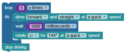
The loop (x times) block allows you to repeat 5 straight lines & 5 angle turns, creating the star shape. Your star's line length is determined by the time parameter of the wait block - the longer the wait time the larger the star. If you want a bigger or smaller star, you can change this value. The rotate block is used because you can now set an angle by entering the value as well as by choosing the angle from the dropdown circle. At the end of your program, the stop driving block will make your S3 stop moving.
Try this program again, but this time place your S3 on a piece of poster board with a Sharpie® in the pen port. You could also place it on a whiteboard using a compatible dry-erase marker. Remember not to use a Sharpie on a whiteboard!
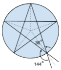 So, where did we get that odd 144° angle? Look at the sketch on the left. If you divide the 360° circle by 5, you can see that the angle between the dotted lines is 72°.
The angle between the lines of the point is half of 72°, or 36°. When the S3 reaches the end of a line in your star (the tip of a point) it turns 180° minus the angle of the point. The angle of the turn is 180°- 36° = 144°.
Study this sketch until this is clear, or do a search for "5-pointed star" to find more resources on the math behind this shape.

Notice in the code above, that the first rotate by radius block has -72° as its rotation value. Clockwise rotation is written as a positive value, while negative values rotate in a counterclockwise direction. This is similar to how percent speed values are positve for forward and negative for backward. What might you imagine is different about using a positive versus a negative radius value? Experiment and find out.
Let’s try an experiment with the second star program we tried (above).

Note that the value in this block was originally 144° in the first two programs. By changing this value to 143°, you may find that your S3 made a slightly better drawing. Every S3 unit is unique, and you might find that different values result in a better outcome when running these tutorial programs. It's up to you to figure out what works best with your robot, using our examples as a guide. This trial-and-error approach is often called optimizing your program.
The best way to discover the purpose of blocks in this example program is to remove them, and then see how that modified program makes your S3 behave. For example, is the stop driving block at the end of this code required?
Is it required in any of the programs in this tutorial? If not, why might it be included and where is it mandatory? Review the Simple Motion with Motors Blocks tutorials that you've already completed to refresh your memory on why we use it. Now let's modify the Curved Star program a bit.
Here you will use two blocks from the MATH category - the math operation block and the number value block. Can you predict what they might do?

The first math operation block adds 2° to the original 73° rotation value. The next math operation block subtracts 2° from the 143° rotation value.
Our additions really made this star shape into art with our subtracting a thing! Don’t you think?
What did you change, and what did you learn? Continue to experiment. Inspiration often strikes by accident, or when you are least expecting it.
Special thanks to Parallax friend Whit Stodghill for his assistance in writing, editing, and testing material for these S3 tutorials.

Links
[1] https://learn.parallax.com/tutorials/robot/scribbler-robot/getting-started-blocklyprop-s3
[2] https://learn.parallax.com/tutorials/robot/scribbler-robot/lights-and-sounds
[3] http://mars.nasa.gov/msl/
[4] http://forrestmims.org/home.html
[5] http://forrestmims.org/publications.html
[6] http://learn.parallax.com/tutorials/robot/scribbler-robot/simple-motion-motors-blocks/drive-there-and-back-again-using-motor
[7] http://learn.parallax.com/tutorials/robot/scribbler-robot/getting-started-blocklyprop-s3/setting-blocklyprop-s3
[8] http://learn.parallax.com/tutorials/robot/scribbler-robot/simple-motion-motors-blocks/driving-basics-drive-and-rotate-blocks