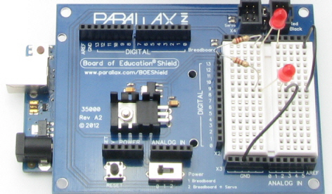
In this chapter, you will use the Board of Education Shield for building and testing circuits with Parallax continuous rotation servos, resistors, and light-emitting diodes. Along the way, you’ll start learning the basics of building circuits and making the Arduino interact with them. By the end of the chapter, you’ll have a pair of servos connected, each with its own signal indicator light, and you’ll be writing sketches to control servo speed and direction.
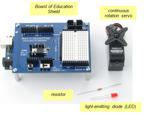
The Board of Education Shield makes it easy to build circuits and connect servos to the Arduino module. In this chapter, you will use it to test servos and indicator lights. Next chapter, you’ll mount the BOE Shield and servos on a robot chassis to build a robot we’ll call the BOE Shield-Bot.
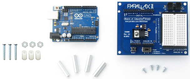
(1) Arduino module
(1) Board of Education Shield
(4) 1″ round aluminum standoffs
(4) pan head screws, 1/4″ 4-40
(3) 1/2″ round nylon spacers*
(3) nylon nuts, 4-40*
(3) pan head screws, 7/8″, 4-40*
(*Items also included in the Boe-Bot to Shield-Bot Retrofit Kit [2])
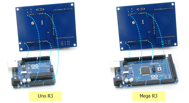
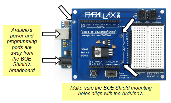
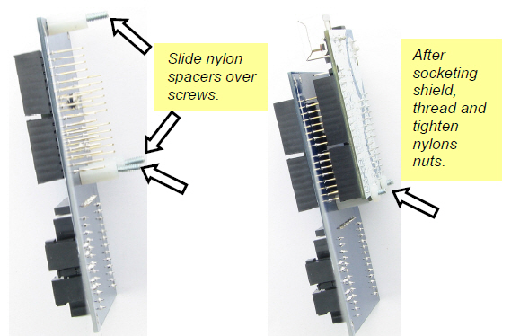
The four groups of pins under the Board of Education Shield plug into the four Arduino socket headers. There are also three board-connection holes in the shield that line up with holes in the Arduino module, designed to connect the two boards together with screws and nylon spacers.
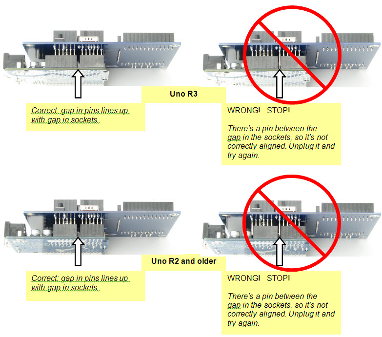
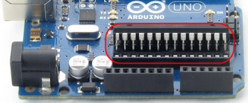
If you have a revision 3 Arduino, it will be labeled UNO R3 or MEGA R3 on the back. R3 boards will have two empty pairs of sockets, closest to the USB and power connectors, after socketing the shield. Earlier versions, such as 2, 1, and Duemilanove, have the same number of sockets as the shield has pins, so there will be no empty sockets left over. If you have an Arduino Mega, the four pin groups will fit into the four headers closest to the USB and power connectors, as shown in the box below.
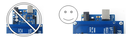
Component placement varies a little bit for the different Arduino models; some can only fit one or two nylon standoffs for holding the boards together. This is okay, but you need to find out which holes you can use before socketing the Board of Education Shield.
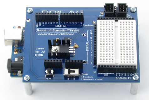
To keep the connected boards up off of the table, we’ll mount tabletop standoffs to each corner of the Board of Education Shield.
Indicator lights give people a way to see a representation of what’s going on inside a device, or patterns of communication between two devices. Next, you will build indicator lights to display the communication signals that the Arduino will send to the servos. If you haven’t ever built a circuit before, don’t worry, this activity shows you how.
A resistor is a component that resists the flow of electricity. This flow of electricity is called current. Each resistor has a value that tells how strongly it resists current flow. This resistance value is called the ohm, and the sign for the ohm is the Greek letter omega: Ω. (Later on you will see the symbol kΩ, meaning kilo-ohm, which is one thousand ohms.)
This resistor has two wires (called leads and pronounced “leeds”), one coming out of each end. The ceramic case between the two leads is the part that resists current flow. Most circuit diagrams use the jagged line symbol with a number label to indicate a resistor of a certain value, a 470 Ω resistor in this case. This is called a schematic symbol. The part drawing on the right is used in some beginner-level texts to help you identify the resistors in your kit, and where to place them when you build circuits.
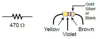
The resistors in your parts kit have colored stripes that indicate what their resistance values are. There is a different color combination for each resistance value. For example, the color code for the 470 Ω resistor is yellow-violet-brown.
There may be a fourth stripe that indicates the resistor’s tolerance. Tolerance is measured in percent, and it tells how far off the part’s true resistance might be from the labeled resistance. The fourth stripe could be gold (5%), silver (10%) or no stripe (20%). For the activities in this book, a resistor’s tolerance does not matter, but its value does.
Each color bar on the resistor's case corresponds to a digit, as listed in the table below.
| Digit | 0 | 1 | 2 | 3 | 4 | 5 | 6 | 7 | 8 | 9 |
| Color | black | brown | red | orange | yellow | green | blue | violet | gray | white |
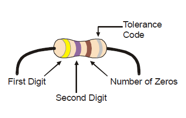
Here’s how to find the resistor’s value, in this case proving that yellow-violet-brown is really 470 Ω:
Yellow-Violet-Brown = 4-7-0 = 470 Ω.
A diode is a one-way electric current valve, and a light-emitting diode (LED) emits light when current passes through it. Since an LED is a one-way current valve, you have to make sure to connect it the right way for it to work as intended.
An LED has two terminals: the anode and the cathode. The anode lead is labeled with the plus-sign (+) in the part drawing, and it is the wide part of the triangle in the schematic symbol. The cathode lead is the pin labeled with a minus-sign (-), and it is the line across the point of the triangle in the schematic symbol.
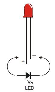
When you build an LED circuit, you will have to make sure the anode and cathode leads are connected to the circuit properly. You can tell them apart by the shape of the LED’s plastic case. Look closely at the case—it’s mostly round, but there is a small flat spot right near one of the leads, and that tells you it’s the cathode. Also note that the LED’s leads are different lengths. Usually, the shorter lead is connected to the cathode.
Always check the LED’s plastic case.
Usually, the longer lead is connected to the LED’s anode, and the shorter lead is connected to its cathode. But sometimes the leads have been clipped to the same length, or a manufacturer does not follow this convention. So, it’s best to always look for the flat spot on the case. If you plug an LED in backwards, it will not hurt it, but it won’t emit light until you plug it in the right way.
The white board with lots of square sockets in it is called a solderless breadboard. This breadboard has 17 rows of sockets. In each row, there are two five-socket groups separated by a trench in the middle. All the sockets in a 5-socket group are connected together underneath with a conductive metal clip. So, two wires plugged into the same 5‑socket group make electrical contact. This is how you will connect components, such as an LED and resistor, to build circuits. Two wires in the same row on opposite sides of the center trench will not be connected.
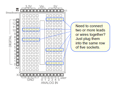
The prototyping area also has black sockets along the top, bottom, and left.
Digital and analog pins are the small pins on the Arduino module’s Atmel microcontroller chip. These pins electrically connect the microcontroller brain to the board.
A sketch can make the digital pins send high or low signals to circuits. In this chapter, we’ll do that to turn lights on and off. A sketch can also make a digital pin monitor high or low signals coming from a circuit; We’ll do that in another chapter to detect whether a contact switch has been pressed or released.
A sketch can also measure the voltages applied to analog pins; we’ll do that to measure light with a phototransistor circuit in another chapter.
(2) LEDs – Red
(2) Resistors, 220 Ω (red-red-brown)
(3) Jumper wires
Always disconnect power to your board before building or modifying circuits!
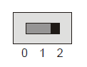
1. Set the BOE Shield’s Power switch to 0.
2. Disconnect the programming cable and battery pack.
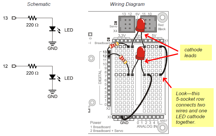
The image below shows the indicator LED circuit schematic on the left, and a wiring diagram example of the circuit built on your BOE Shield’s prototyping area on the right.
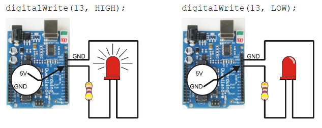
The next picture will give you an idea of what is going on when you program the Arduino to control the LED circuit. Imagine that you have a 5 volt (5 V) battery. The Board of Education Shield has a device called a voltage regulator that supplies 5 volts to the sockets labeled 5V. When you connect the anode end of the LED circuit to 5 V, it’s like connecting it to the positive terminal of a 5 V battery. When you connect the circuit to GND, it’s like connecting to the negative terminal of the 5 V battery.
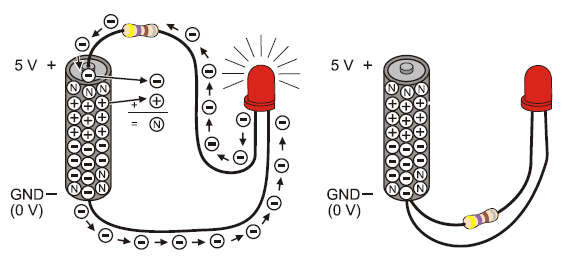
On the left side of the picture, one LED lead is connectd to 5 V and the other to GND. So, 5 V of electrical pressure causes electrons to flow through the circuit (electric current), and that current causes the LED to emit light. The circuit on the right side has both ends of the LED circuit connected to GND. This makes the voltage the same (0 V) at both ends of the circuit. No electrical pressure = no current = no light.
You can connect the LED to a digital I/O pin and program the Arduino to alternate the pin’s output voltage between 5 V and GND. This will turn the LED light on/off, and that’s what we’ll do next.
Volts is abbreviated V.
When you apply voltage to a circuit, it’s like applying electrical pressure. By convention, 5 V means “5 V higher than ground.” Ground, often abbreviated GND, is considered 0 V.
Ground is abbreviated GND.
The term ground originated with electrical systems where this connection is actually a metal rod that has been driven into the ground. In portable electronic devices, ground is commonly used to refer to connections that go to the battery supply’s negative terminal.
Current refers to the rate at which electrons pass through a circuit.
You will often see measurements of current expressed in amps, which is abbreviated A. The currents you will use here are measured in thousandths of an amp, or milliamps. For example, 10.3 mA passes through the circuit shown above.
Let’s start with a sketch that makes the LED circuit connected to digital pin 13 turn on/off. First, your sketch has to tell the Arduino to set the direction of pin 13 to output, using the pinMode function: pinMode(pin, mode). The pin parameter is the number of a digital I/O pin, and mode must be either INPUT or OUTPUT.
void setup()                      // Built-in initialization block
{
  pinMode(13, OUTPUT);            // Set digital pin 13 -> output
}
Now that digital pin 13 is set to output, we can use digitalWrite to turn the LED light on and off. Take a look at the picture below. On the left, digitalWrite(13, HIGH) makes the Arduino’s microcontroller connect digital pin 13 to 5 V, which turns on the LED. On the right, it shows how digitalWrite(13, LOW) makes it connect pin 13 to GND (0 V) to turn the LED off.
Here’s the loop function from the next sketch. First, digitalWrite(13, HIGH) turns the light on, delay(500) keeps it on for a half-second. Then digitalWrite(13, LOW) turns it off, and that’s also followed by delay(500). Since it’s inside the loop function’s block, the statements will repeat automatically. The result? The light will flash on/off once every second.
void loop()                        // Main loop auto-repeats
{
  digitalWrite(13, HIGH);          // Pin 13 = 5 V, LED emits light
  delay(500);                      // ..for 0.5 seconds
  digitalWrite(13, LOW);           // Pin 13 = 0 V, LED no light
  delay(500);                      // ..for 0.5 seconds
}
/*
 Robotics with the BOE Shield - HighLowLed
 Turn LED connected to digital pin 13 on/off once every second.
 */

void setup()                                 // Built-in initialization block
{
  pinMode(13, OUTPUT);                       // Set digital pin 13 -> output
}

void loop()                                  // Main loop auto-repeats
{
  digitalWrite(13, HIGH);                    // Pin 13 = 5 V, LED emits light
  delay(500);                                // ..for 0.5 seconds
  digitalWrite(13, LOW);                     // Pin 13 = 0 V, LED no light
  delay(500);                                // ..for 0.5 seconds
}
A timing diagram is a graph that relates a signal's high and low stages to time. This timing diagram shows you a 1000 ms slice of the HIGH (5 V) and LOW (0 V) signals from the sketch HighLowLed. Can you see how delay(500) is controlling the blink rate?
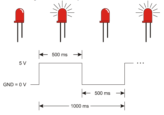
How would you make the LED blink twice as fast? How about reducing the delay function’s ms parameters by half?
Blinking the pin 12 LED is a simple matter of changing the pin parameter in the pinMode and two digitalWrite function calls.
You can also make both LEDs blink at the same time.
  pinMode(13, OUTPUT);         // Set digital pin 13 -> output
  pinMode(12, OUTPUT);         // Set digital pin 12 -> output
  digitalWrite(13, HIGH);      // Pin 13 = 5 V, LED emits light
  digitalWrite(12, HIGH);      // Pin 12 = 5 V, LED emits light
  delay(500);                  // ..for 0.5 seconds
  digitalWrite(13, LOW);       // Pin 13 = 0 V, LED no light
  digitalWrite(12, LOW);       // Pin 12 = 0 V, LED no light
  delay(500);                  // ..for 0.5 seconds
How would you modify the sketch again to turn one LED on while the other turns off? One circuit will need to receive a HIGH signal while the other receives a LOW signal.
The high and low signals that control servo motors must last for very precise periods of time. That’s because a servo motor measures how long the signal stays high, and uses that as an instruction for how fast, and in which direction, to turn its motor.
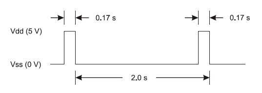
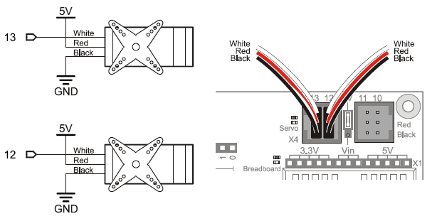
This timing diagram shows a servo signal that would make your Shield-Bot’s wheel turn full speed counterclockwise. There’s one big difference though: all the signals in this timing diagram last 100 times longer than they would if they were controlling a servo. This slows it down enough so that we can see what’s going on.
/*
    Robotics with the BOE Shield - ServoSlowMoCcw
    Send 1/100th speed servo signals for viewing with an LED.
 */

void setup()                                 // Built in initialization block
{
  pinMode(13, OUTPUT);                       // Set digital pin 13 -> output
}

void loop()                                  // Main loop auto-repeats
{
  digitalWrite(13, HIGH);                    // Pin 13 = 5 V, LED emits light
  delay(170);                                // ..for 0.17 seconds
  digitalWrite(13, LOW);                     // Pin 13 = 0 V, LED no light
  delay(1830);                               // ..for 1.83 seconds
}
Alright, how about 1/10th speed instead of 1/100th speed?
Is the LED blinking 10 times faster now? Divide by 10 again for a full speed servo signal—we’ll have to round the numbers a bit:
Now you can see what the servo signal looks like with the indicator LED. The LED is flickering so fast, it’s just a glow. Since the high signal is 2 ms instead of 1.7 ms, it’ll be a little brighter than the actual servo control signal—the light is spending more time on. We could use this signal and programming technique to control a servo, but there’s an easier, more precise way. Let’s try it with LEDs first.
A better way to generate servo control signals is to include the Arduino Servo library in your sketch, one of the standard libraries of pre-written code bundled with the Arduino software.
We want to take a closer look at the Servo library.
attach()
writeMicroseconds()
detach()
Servos have to receive high-pulse control signals at regular intervals to keep turning. If the signal stops, so does the servo. Once your sketch uses the Servo library to set up the signal, it can move on to other code, like delays, checking sensors, etc. Meanwhile, the servo keeps turning because the Servo library keeps running in the background. It regularly interrupts the execution of other code to initiate those high pulses, doing it so quickly that it’s practically unnoticeable.
Using the Servo library to send servo control signals takes four steps:
#include <Servo.h> // Include servo library
Servo servoLeft; // Declare left servo
servoLeft.attach(13); // Attach left signal to pin 13
servoLeft.writeMicroseconds(1500); // 1.5 ms stay-still signal
Seconds, Milliseconds, Microseconds
A millisecond is a one-thousandth of a second, abbreviated ms.
A microsecond is a one-millionth of a second, abbreviated μs.
There are 1000 microseconds (μs) in 1 millisecond (ms).
There are 1,000,000 microseconds in 1 second (s).
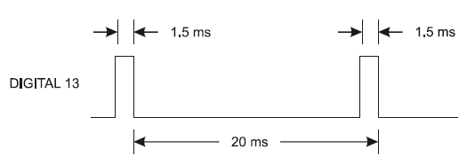
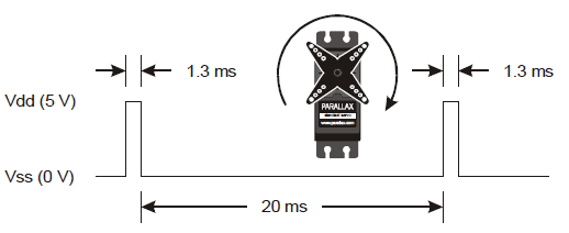
For calibrating servos, your sketch will need to send signals with 1.5 ms pulses. Take a look at the timing diagram below. This stay-still signal’s high pulses last 1.5 ms. That’s halfway between the 1.7 ms full-speed-counterclockwise and 1.3 ms full-speed-clockwise pulses.
/*
 Robotics with the BOE Shield – LeftServoStayStill
 Generate signal to make the servo stay still for centering.
 */

#include <Servo.h>                           // Include servo library

Servo servoLeft;                             // Declare left servo

void setup()                                 // Built in initialization block
{
  servoLeft.attach(13);                      // Attach left signal to pin 13
  servoLeft.writeMicroseconds(1500);         // 1.5 ms stay still signal
}

void loop()                                  // Main loop auto-repeats
{                                            // Empty, nothing needs repeating
}
You’ll be using this code a lot, so it’s a good idea to practice declaring an instance of Servo, attaching the signal to a pin, and setting the pulse duration.
Servo servoRight; // Declare right servo
servoRight.attach(12); // Attach right signal to pin 12
servoRight.writeMicroseconds(1500); // 1.5 ms stay still signal
/*
 Robotics with the BOE Shield – BothServosStayStill
 Generate signals to make the servos stay still for centering.
 */

#include <Servo.h>                           // Include servo library

Servo servoLeft;                             // Declare left servo signal
Servo servoRight;                            // Declare right servo signal

void setup()                                 // Built in initialization block
{
  servoLeft.attach(13);                      // Attach left signal to pin 13
  servoRight.attach(12);                      // Attach left signal to pin 12

  servoLeft.writeMicroseconds(1500);         // 1.5 ms stay still sig, pin 13
  servoRight.writeMicroseconds(1500);        // 1.5 ms stay still sig, pin 12
}

void loop()                                  // Main loop auto-repeats
{                                            // Empty, nothing needs repeating
}
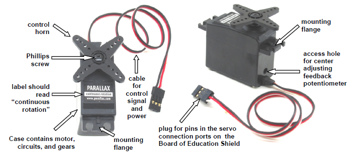
From the robot navigation standpoint, continuous rotation servos offer a great combination of simplicity, usefulness and low price. The Parallax continuous rotation servos are the motors that will make the BOE Shield-Bot’s wheels turn, under Arduino control.
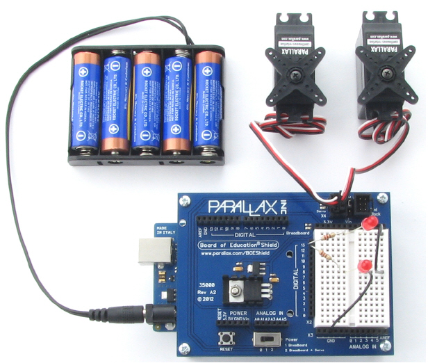
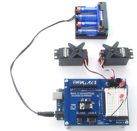
In this activity, you will connect your servos to the Board of Education Shield’s servo ports, which will connect them to supply voltage, ground, and a signal pin. You will also connect a battery supply to your Arduino because, under certain conditions, servos can end up demanding more current than a USB supply is designed to deliver.
Standard Servos vs. Continuous Rotation Servos
Standard servos are designed to receive electronic signals that tell them what position to hold. These servos control the positions of radio controlled airplane flaps, boat rudders, and car steering. Continuous rotation servos receive the same electronic signals, but instead turn at certain speeds and directions. Continuous rotation servos are handy for controlling wheels and pulleys.
Servo Control Horn, 4-point Star vs. Round
It doesn’t make a difference. So long as it is labeled “continuous rotation” it’s the servo for your BOE Shield-Bot. You’ll remove the control horn and replace it with a wheel.
Leave the LED circuits from the last activity on your board. They will be used later to monitor the signals the Arduino sends to the servos to control their motion.
(2) Parallax continuous rotation servos
BOE Shield with built and tested LED indicator circuits from the previous activity
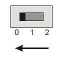
Between the servo headers on the BOE Shield is a jumper that connects the servo power supply to either Vin or 5V. To move it, pull it upwards and off the pair of pins it covers, then push it onto the pair of pins you want it to rest on. The BOE Shield-Bot’s battery pack will supply 7.5 V. Since the servos are rated for 4–6 V, we want to make sure the jumper is set to 5V. Also, a steady 5 V voltage supply will support a consistent servo speed, and more accurate navigation, than voltage that varies as batteries discharge.
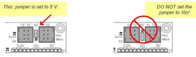
The picture below shows the schematic of the circuit you create by plugging the servos into ports 13 and 12 on the BOE Shield. Pay careful attention to wire color as you plug in the cables: the black wire should be at the bottom, and the white one should be at the top.
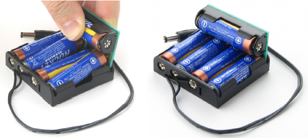
To properly power the servos, you’ll need to switch to an external battery pack now. When servos make sudden direction changes or push against resistance to rotation, they can draw more current than a USB port is designed to supply. Also, it would be no fun for the BOE Shield-Bot to be tethered to the computer forever! So, from here on out we’ll be using an external battery pack with five 1.5 V AA batteries. This will supply your system with 7.5 V and plenty of current for the voltage regulators and servos. From here forward, remember two things:
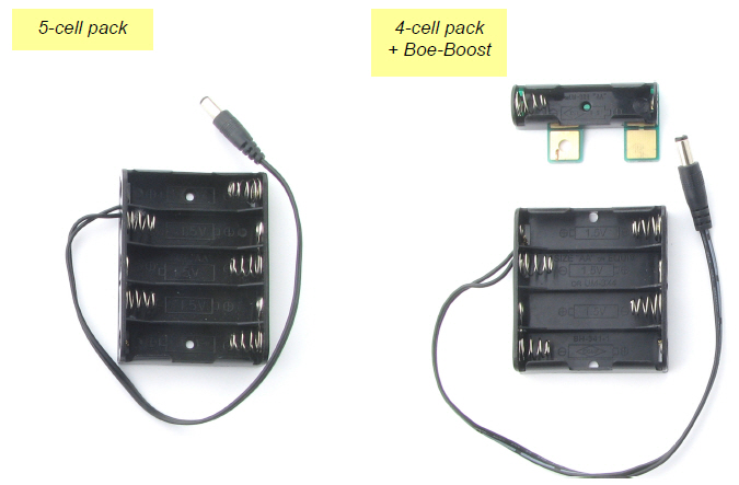
Rechargeable Options
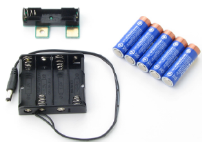
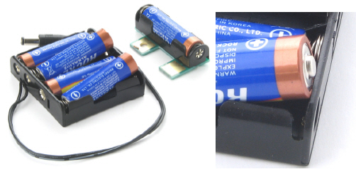
The thrifty Boe-Boost (#30078) allows you to add another cell in series with a 4-cell or 5-cell pack. Adding a 6th 1.2 V AA rechargeable cell to a 5-cell pack will supply 6 x 1.2 = 7.2 V.
The Li-ion Boe-Bot Power Pack-Charger (#28988) combines a lithium-ion battery pack and recharger in one board that you can mount under your Shield-Bot.
CAUTION: AC powered DC supplies are not recommended for the BOE Shield-Bot.
Some DC supplies provide much higher voltage than their rating. The BOE Shield-bot is designed for use with a 7.2–7.5 V battery supply. It will work with higher supply voltages at low loads, but the servo loads can heat up the regulator until it shuts off to protect itself.
(5) AA alkaline batteries
(1) 5-cell battery pack
(1) Boe-Boost
(1) 4-cell battery pack
(5) AA alkaline batteries

In this activity, you will run a sketch that sends the “stay-still” signal to the servos. You will then use a screwdriver to adjust the servos so that they actually stay still. This is called centering the servos. After the adjustment, you will run test sketches that will turn the servos clockwise and counterclockwise at various speeds.
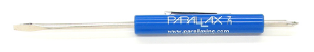
You’ll need a Phillips #1 point screwdriver with a 1/8″ (3.18 mm) or smaller shaft.
If a servo has not yet been centered, it may turn, vibrate, or make a humming noise when it receives the “stay-still” signal.
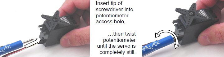
What’s a Potentiometer?
A potentiometer is kind of like an adjustable resistor with a moving part, such as a knob or a sliding bar, for setting the resistance. The Parallax continuous rotation servo’s potentiometer is a recessed knob that can be adjusted with a small Phillips screwdriver tip. Learn more about potentiometers in What’s a Microcontroller? and Basic Analog and Digital at www.parallax.com.
/*
 Robotics with the BOE Shield – RightServoStayStill
 Transmit the center or stay still signal on pin 12 for center adjustment.
 */

#include <Servo.h>                           // Include servo library

Servo servoRight;                            // Declare right servo

void setup()                                 // Built-in initialization block
{
  servoRight.attach(12);                     // Attach right signal to pin 12
  servoRight.writeMicroseconds(1500);        // 1.5 ms stay still signal
}

void loop()                                  // Main loop auto-repeats
{                                            // Empty, nothing needs repeating
}
There’s one last thing to do before assembling your BOE Shield-Bot, and that’s testing the servos. In this activity, you will run sketches that make the servos turn at different speeds and directions. This is an example of subsystem testing—a good habit to develop.
Subsystem testing is the practice of testing the individual components before they go into the larger device. It’s a valuable strategy that can help you win robotics contests. It’s also an essential skill used by engineers to develop everything from toys, cars, and video games to space shuttles and Mars roving robots. Especially in more complex devices, it can become nearly impossible to figure out a problem if the individual components haven’t been tested beforehand. In aerospace projects, for example, disassembling a prototype to fix a problem can cost hundreds of thousands, or even millions, of dollars. In those kinds of projects, subsystem testing is rigorous and thorough.
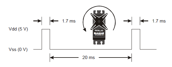
This timing diagram shows how a Parallax continuous rotation servo turns full speed clockwise when you send it 1.3 ms pulses. Full speed typically falls in the 50 to 60 RPM range.
What’s RPM? Revolutions Per Minute—the number of full rotations turned in one minute.
What’s a pulse train? Just as a railroad train is a series of cars, a pulse train is a series of pulses (brief high signals).
/*
 Robotics with the BOE Shield – LeftServoClockwise
 Generate a servo full speed clockwise signal on digital pin 13.
 */

#include <Servo.h>                           // Include servo library

Servo servoLeft;                             // Declare left servo

void setup()                                 // Built in initialization block
{
  servoLeft.attach(13);                      // Attach left signal to pin 13
  servoLeft.writeMicroseconds(1300);         // 1.3 ms full speed clockwise
}

void loop()                                  // Main loop auto-repeats
{                                            // Empty, nothing needs repeating
}
/*
 Robotics with the BOE Shield – RightServoClockwise
 Generate a servo full speed clockwise signal on digital pin 12.
 */

#include <Servo.h>                           // Include servo library

Servo servoRight;                            // Declare left servo

void setup()                                 // Built in initialization block
{
  servoRight.attach(12);                     // Attach left signal to pin 12
  servoRight.writeMicroseconds(1300);        // 1.3 ms full speed clockwise
}

void loop()                                  // Main loop auto-repeats
{                                            // Empty, nothing needs repeating
}
For BOE Shield-Bot navigation, we need to control both servos at once.
 /*
 Robotics with the BOE Shield – ServosOppositeDirections
 Generate a servo full speed counterclockwise signal with pin 13 and
 full speed clockwise signal with pin 12.
 */

#include <Servo.h>                           // Include servo library

Servo servoLeft;                             // Declare left servo signal
Servo servoRight;                            // Declare right servo signal

void setup()                                 // Built in initialization block
{
  servoLeft.attach(13);                      // Attach left signal to pin 13
  servoRight.attach(12);                     // Attach right signal to pin 12

  servoLeft.writeMicroseconds(1700);         // 1.7 ms -> counterclockwise
  servoRight.writeMicroseconds(1300);        // 1.3 ms -> clockwise
}

void loop()                                  // Main loop auto-repeats
{                                            // Empty, nothing needs repeating
}
This opposite-direction control will be important soon. Think about it: when the servos are mounted on either side of a chassis, one will have to rotate clockwise while the other rotates counterclockwise to make the BOE Shield-Bot roll in a straight line. Does that seem odd? If you can’t picture it, try this:
Pulse Width Modulation
Adjusting the property of a signal to carry information is called modulation. We’ve discovered that servo control signals are a series of high pulses separated by low resting states. How long the high pulse lasts—how wide the high pulse looks in a timing diagram—determines the speed and direction that the servo turns. That adjustable pulse width carries the servo setting information. Therefore, we can say that servos are controlled with pulse width modulation.
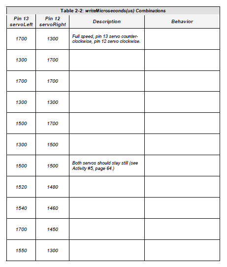
Different combinations of writeMicroseconds us parameters will be used repeatedly for programming your BOE Shield-Bot’s motion. By testing several possible combinations and filling in the Description column of Table 2‑2, you will become familiar with them and build a reference for yourself. You’ll fill in the Behavior column later on, when you see how the combinations make your assembled BOE Shield-Bot move.
It’s easy to control how long the servos run when using the Servo library. Once set, a servo will maintain its motion until it receives a new setting. So, to make a servo run for a certain length of time, all you have to do is insert a delay after each setting.
/*
 Robotics with the BOE Shield – ServoRunTimes
 Generate a servo full speed counterclockwise signal with pin 13 and
 full speed clockwise signal with pin 12.
 */

#include <Servo.h>                           // Include servo library

Servo servoLeft;                             // Declare left servo signal
Servo servoRight;                            // Declare right servo signal

void setup()                                 // Built in initialization block
{
  servoLeft.attach(13);                      // Attach left signal to pin 13
  servoRight.attach(12);                     // Attach right signal to pin 12

  servoLeft.writeMicroseconds(1300);         // Pin 13 clockwise
  servoRight.writeMicroseconds(1300);        // Pin 12 clockwise
  delay(3000);                               // ..for 3 seconds
  servoLeft.writeMicroseconds(1700);         // Pin 13 counterclockwise
  servoRight.writeMicroseconds(1700);        // Pin 12 counterclockwise
  delay(3000);                               // ..for 3 seconds
  servoLeft.writeMicroseconds(1500);         // Pin 13 stay still
  servoRight.writeMicroseconds(1500);        // Pin 12 stay still
}

void loop()                                  // Main loop auto-repeats
{                                            // Empty, nothing needs repeating
}
The focus of this chapter was calibrating and testing the servos, and building indicator lights to monitor the servo signals. In addition to some hardware setup, many concepts related to electronics, programming, and even a few good engineering concepts were introduced along the way.
Hardware Setup
Electronics
Programming
Engineering
Question Solutions
digitalWrite(13, HIGH) // 5 V
digitalWrite(13, LOW)  // 0 V
Exercise Solutions
void loop()                    // Main loop auto-repeats
{                              // 200 ms -> 5 blinks/second
  digitalWrite(13, HIGH);      // Pin 13 = 5 V, LED emits light
  delay(50);                   // ..for 0.05 seconds
  digitalWrite(13, LOW);       // Pin 13 = 0 V, LED no light
  delay(150);                  // ..for 0.15 seconds
}
void setup()                   // Built in initialization block
{
  servoLeft.attach(13);        // Attach left signal to pin 13
  servoRight.attach(12);       // Attach right signal to pin 12

  servoLeft.writeMicroseconds(1300);  // 1.3 ms -> clockwise
  servoRight.writeMicroseconds(1500); // 1.5 ms -> stop
  delay(1200);                        // ..for 1.2 seconds
  servoLeft.writeMicroseconds(1500);  // 1.5 ms -> stop
}
void setup()                   // Built in initialization block
{
  servoLeft.attach(13);        // Attach left signal to pin 13
  servoRight.attach(12);       // Attach right signal to pin 12

  servoLeft.writeMicroseconds(1700);  // 1.7 ms -> cc-wise
  servoRight.writeMicroseconds(1300); // 1.3 ms -> clockwise
  delay(1500);                        // ..for 1.5 seconds
  servoRight.writeMicroseconds(1700); // 1.7 ms -> cc-wise
  delay(1500);
  servoLeft.writeMicroseconds(1500);  // 1.5 ms -> stop
  servoRight.writeMicroseconds(1500); // 1.5 ms -> stop
}
Project Solutions
/*
 Robotics with the BOE Shield – Chapter 2, Project 1
 Generate a servo full speed counterclockwise signal with pin 13 and
 full speed clockwise signal with pin 12.
 */

#include <Servo.h>                    // Include servo library

Servo servoLeft;                      // Declare left servo signal
Servo servoRight;                     // Declare right servo signal

void setup()                          // Built in initialization block
{
  servoLeft.attach(13);               // Attach left signal to pin 13
  servoRight.attach(12);              // Attach right signal to pin 12

  servoLeft.writeMicroseconds(1700);  // Pin 13 counterclockwise
  servoRight.writeMicroseconds(1300); // Pin 12 clockwise
  delay(3000);                        // ..for 3 seconds
  servoLeft.detach();                 // Stop servo signal to pin 13
  servoRight.detach();                // Stop servo signal to pin 12
}

void loop()                           // Main loop auto-repeats
{                                     // Empty, nothing needs repeating
}

Links
[1] https://learn.parallax.com/sites/default/files/content/shield/robo_ch2/code/RoboticsBOEShield_Ch2_20120229.zip
[2] http://learn.parallax.com/tutorials/robot/shield-bot/boe-bot-shield-bot-retrofit-kit-arduino-uno
[3] https://learn.parallax.com/184
[4] https://learn.parallax.com/185