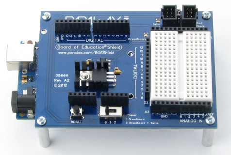
The Board of Education Shield makes it easy to build circuits and connect servos to the Arduino module. In this chapter, you will use it to test servos and indicator lights. Next chapter, you’ll mount the BOE Shield and servos on a robot chassis to build a robot we’ll call the BOE Shield-Bot.
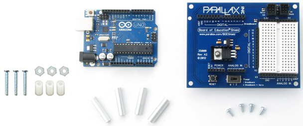
(1) Arduino module
(1) Board of Education Shield
(4) 1″ round aluminum standoffs
(4) pan head screws, 1/4″ 4-40
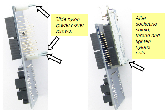
(3) 1/2″ round nylon spacers*
(3) nylon nuts, 4-40*
(3) pan head screws, 7/8″, 4-40*
(*Items also included in the Boe-Bot to Shield-Bot Retrofit Kit [1])
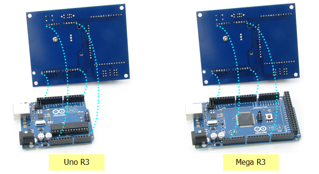
The four groups of pins under the Board of Education Shield plug into the four Arduino socket headers. There are also three board-connection holes in the shield that line up with holes in the Arduino module, designed to connect the two boards together with screws and nylon spacers.
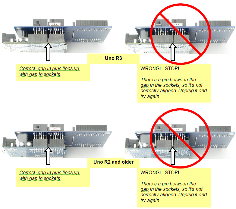
If you have a revision 3 Arduino, it will be labeled UNO R3 or MEGA R3 on the back. R3 boards will have two empty pairs of sockets, closest to the USB and power connectors, after socketing the shield. Earlier versions, such as 2, 1, and Duemilanove, have the same number of sockets as the shield has pins, so there will be no empty sockets left over. If you have an Arduino Mega, the four pin groups will fit into the four headers closest to the USB and power connectors, as shown in the box below.
Component placement varies a little bit for the different Arduino models; some can only fit one or two nylon standoffs for holding the boards together. This is okay, but you need to find out which holes you can use before socketing the Board of Education Shield.
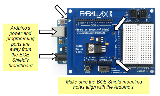
To keep the connected boards up off of the table, we’ll mount tabletop standoffs to each corner of the Board of Education Shield.

Links
[1] http://learn.parallax.com/tutorials/robot/shield-bot/boe-bot-shield-bot-retrofit-kit-arduino-uno