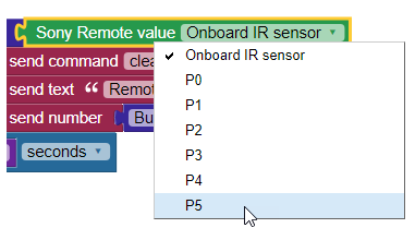
Up until now, we’ve used the Sony Remote value block to receive signals from the S3 onboard IR receiver. We also learned that IR remotes work in a “line of sight” method - meaning that the Sony remote must face the IR receiver on the front of the S3 robot.
We might resolve this directional limitation by having an IR Sensor that could “see” the remote’s signal from any direction. Luckily, the S3 comes with a hacker port that allows you to easily add external sensors to your S3.
To complete this tutorial, in addition to your S3 and Sony IR Remote, you will need the following supplies:
On a personal note - The first solution that I came up with to overcome the line of sight problem, was to place four (4) IR receivers oriented front, back, left, and right. I wasn’t sure how to wire this circuit, so I sent an email to some Parallax friends. I got back a response almost immediately! My friend Ben (who is actually one of the members of the Parallax Team that designed the S3) sent me the idea of the laying a single sensor (i.e., one (1) sensor) on its back facing straight up. It is the idea shown here and it works well, is less expensive than needing four. That is the way real engineers always try to think!
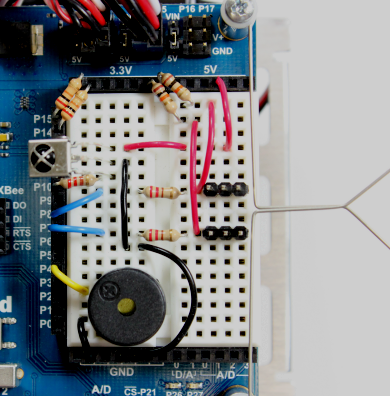
It also turns out the idea is documented here on Learn in a tutorial for a different robot [3]. Here is a photo of an ActivityBot setup to receive IR remote signals and do some other things too! This is a view of the ActivityBot’s breadboard area with the circuit built. It shows the IR receiver facing straight up, just like we're going to do here.
It always a good idea to “get a little help from your friends!” You’ll learn new things. Asking others or visiting Learn and studying the examples there is a way to get help when you need it.
The infrared receiver needs three connections: 5V, GND, and an I/O pin to read the signal it sends:
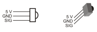
The drawing to the left is called a pinout diagram and it shows symbolically where each pin is supposed to connect. The drawing to the right represents the same information in a more 3-dimensional way.
The circuitry inside the S3 makes it safe to connect the infrared receiver's signal pin to your S3's 3.3V Propeller I/O pin without adding a resistor, even though the sensor itself is powered by 5V. In our S3 circuit, this required resistance is built into the hacker port, so we do not need to connect an external one. When using other Propeller boards or chips, you will need to provide the resistor to protect the chip - see below.
When working with sensors, especially unfamiliar ones, always check their datasheets or product guides to make sure you understand how to safely connect them to your microcontroller. A sensor that requires 5V for operation can damage a 3.3V microcontroller like the Propeller if the proper protection is not provided in the circuit. Many Parallax sensors and microcontrollers have datasheets or product guides available on their product pages. Visit the Parallax website [4] and search the product name or number to find them easily.
Note: Be mindful of the IR Receiver's pinout as compared to the pinout of the hacker port. Look at the pin labels for both the receiver and hacker port to be sure they are connected properly before you turn on your robot. The receiver's pins are configured differently than the hacker port's will be.
Here is the pinout diagram of the S3’s Hacker Port, taken from the S3 User Guide included with your Scribbler. (See What's A Hacker Port?) It is the nearest and neatest choice.

If you have multi-colored jumper wires, use a red jumper wire to make the 5V connection, a black jumper wire to make the G (Ground) connection and a white or yellow jumper wire to make the signal to P5 connection. Refer to the hacker port diagram above and the receiver pinout above to be sure you're making the proper connections.
Note: The GND-PWR-SIGNAL arrangement is standard for many Parallax 3-pin sensors, but the pins are oriented differently on the IR Sensor. So again, be mindful of the IR Receiver's pinout as compared to the pinout of the hacker port!
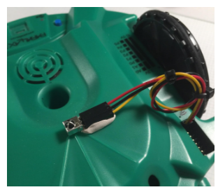
Mount the IR Receiver on the top of the S3, with the receiver's domed side pointing directly up. Use a dot of poster tack putty or double stick tape. The cables can be tied in a loop to keep them out of the way. This makes its small dome visible (remember - direct line of sight) in all directions and from above. The hack is perfect for controlling the S3 with our Sony remote from any direction.
When you have completed this process, carefully check the whole circuit before powering on the S3.
Let’s test our S3’s new external IR receiver and our SONY-programmed remote.
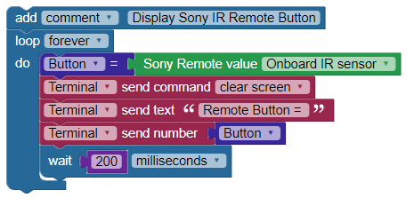
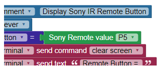
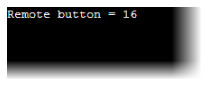
As earlier in the tutorial, you should see the remote button number displayed in the Terminal.
If so, the Hack is successful! If not, turn off your S3 and carefully check everything. Pay particular attention to the how the pins on the external IR sensor are connected with the cable to the pins on the hacker port. Make sure the signal pin, Ground, 5V connections are in proper order. This is another sort of debugging process – debugging the hardware.
It’s pretty nice not having to chase the S3 around - always trying to be in front of it, isn’t it? This ability to add external sensors to your S3 robot is one of its most powerful new features. As you continue to work with the S3, you will likely find many ways to expand on basic programs using the Hacker Port.

Links
[1] https://www.parallax.com/product/350-00039
[2] https://www.parallax.com/product/800-00062
[3] http://learn.parallax.com/tutorials/robot/activitybot/remote-control-rock-talk-and-roll-activitybot
[4] https://www.parallax.com