This tutorial shows you how to add an array of four QTI sensors to your ActivityBot. These sensors can differentiate between dark and light surfaces. With a BlocklyProp program, your ActivityBot robot can use the QTI sensors to follow a black electrical tape line on a light background.

This is a bonus tutorial to follow BlocklyProp Robotics with the ActivityBot [1].
You will be ready to combine QTI line following with other sensors for more advanced projects, like ActivityBot 360° Line Following with Color Sensing [5].
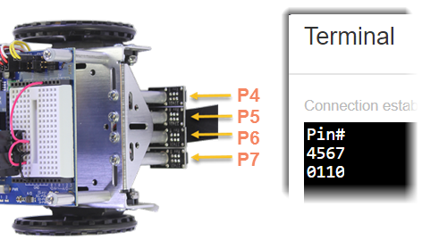
Each QTI sensor is connected to a post that is mounted on the underside of the chassis. This positions the sensors right above the ground surface.
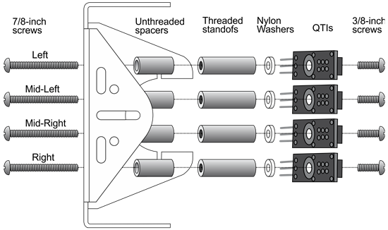
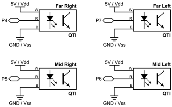
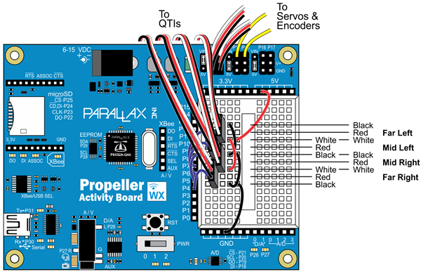
Each QTI sensor needs to connect to to 5 V power, a Propeller I/O pin, and ground. For this, you will use the four 3-pin headers from the kit to build ports on the breadboard for each sensor.
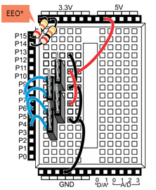
Once you have made all the connections, it is time to test them before trying line-following.
Now it is time to test the QTI sensors.
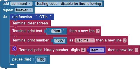
The white paper will reflect infrared light, while the black line will absorb it. Each QTI sensor emits infrared light, then looks for a reflection. When a QTI sensor is over a black line, it will return a "1" and when it is over a white surface, it will return a "0."
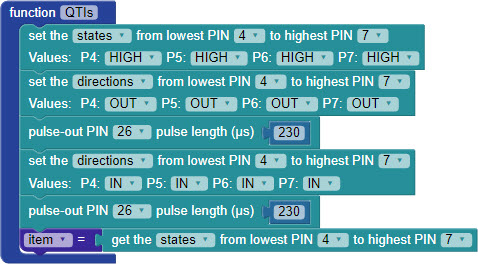
The QTIs function starts by setting the I/O pin states for all four QTI sensors to HIGH, with the direction OUT. This causes each QTI sensor to turn on its infrared LED. The pulse-out PIN 26 pulse length µs 230 block keeps the LEDs on for just a 230 microsecond flash. (We could not use the pause block here, because its shortest duration is 1 millisecond, which is 1000 microseconds).
After that, the I/O pin directions are set to IN (input) for another 230 microseconds. Each QTI sensor is looking for its infrared flash's reflection, and reports I/O pin as a zero if the reflection is seen and a 1 if it is not.
Then, the states of the four I/O pins are saved in the item variable as a four-digit binary number. So, each time through the drive routine's loop, the QTIs function updates the item variable before it gets used for navigation with the switch...case block.
Now that you know your QTI sensors are wired properly, it's time to build the line-following code. It is long, so let's build it a few sections at a time.
You can download the code, but you should still read what's happening below so you know what sections to enable, and how it works.
Project29631-QTI-Line-Follow.svg [7]

Instead of displaying the sensor states, we'll now use that 4-bit binary number to make navigation decisions. The item variable plugs into a switch...case block with nine different case options, shown in the table. The binary number determines the right and left variable values. Those variables will help adjust the robot drive values to keep your ActivityBot on the black line.
| binary | left = | right = | behavior |
|---|---|---|---|
| 1000 | 16 | 32 | pivot left |
| 1100 | 32 | 48 | sharp left |
| 1110 | 48 | 64 | left |
| 0100 | 64 | 64 | slight left |
| 0110 | 64 | 64 | forward |
| 0010 | 64 | 64 | slight right |
| 0111 | 64 | 48 | right |
| 0011 | 48 | 32 | sharp right |
| 0001 | 32 | 16 | pivot right |
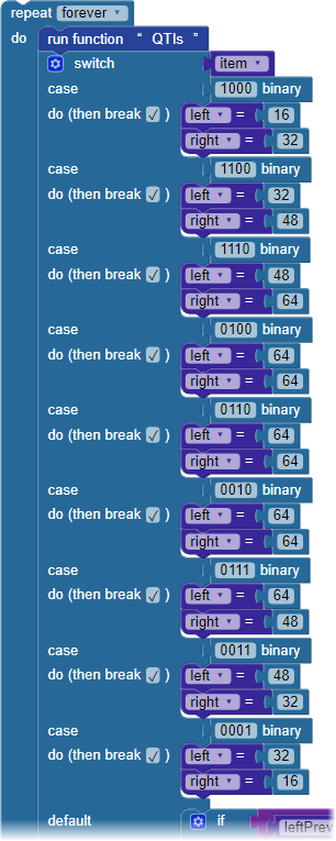

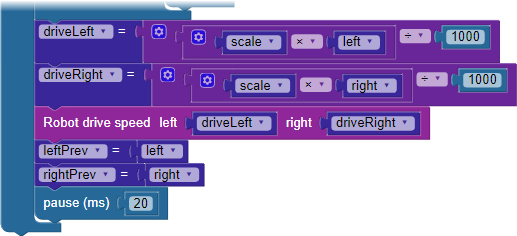
Here, the values of left and right from the switch...case block factor into the driveRight and driveLeft variables that actually set each wheel's speed. By adjusting the initial value of scale at the top of the code. you can fine-tune the robot's performance. Finally, just before the pause block, the values of left and right are saved in leftPrev and rightPrev before the loop repeats.
There are several places you can make adjustments to the code to fine-tune your robot's line-following performance. Use Save As to make copies of your project before experimenting with the adjustments.
If you take a look at the values assigned to the left and right variables for each case, you can see a pattern.
Now that you are sure your line follower is working well, try experimenting with arrays as another approach to building your BlocklyProp program. Think of an array as a numbered list of data elements. Your code can refer to a particular data element by its list number. Now, imagine your list numbering uses binary numbers instead of decimal numbers.
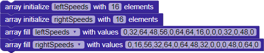
Remember the table of wheel speeds from the previous page? The binary numbers created by the QTI sensors can be used as array list numbers, and the left and right wheel speed values can be used as array elements.
| binary | left = | right = | behavior |
|---|---|---|---|
| 1000 | 16 | 32 | pivot left |
| 1100 | 32 | 48 | sharp left |
| 1110 | 48 | 64 | left |
| 0100 | 56 | 64 | slight left |
| 0110 | 64 | 64 | forward |
| 0010 | 64 | 56 | slight right |
| 0111 | 64 | 48 | right |
| 0011 | 48 | 32 | sharp right |
| 0001 | 32 | 16 | pivot right |
The binary numbers in the column above represent the output of the four QTI sensors - but binary is also a way to represent an integer. The next table shows each of the binary numbers and their decimal equivalents:
| binary | decimal | left = | right = | behavior |
|---|---|---|---|---|
| 1000 | 8 | 16 | 32 | pivot left |
| 1100 | 12 | 32 | 48 | sharp left |
| 1110 | 14 | 48 | 64 | left |
| 0100 | 4 | 56 | 64 | slight left |
| 0110 | 6 | 64 | 64 | forward |
| 0010 | 2 | 64 | 56 | slight right |
| 0111 | 7 | 64 | 48 | right |
| 0011 | 3 | 48 | 32 | sharp right |
| 0001 | 1 | 32 | 16 | pivot right |
Next, we will sort the table by the decimal representation of the QTI sensors’ output, and leave blanks for the in-between numbers:
| binary | decimal | left = | right = | behavior |
|---|---|---|---|---|
| 0 | 0 | 0 | ||
| 0001 | 1 | 32 | 16 | pivot right |
| 0010 | 2 | 64 | 56 | slight right |
| 0011 | 3 | 48 | 32 | sharp right |
| 0100 | 4 | 56 | 64 | slight left |
| 5 | 0 | 0 | ||
| 0110 | 6 | 64 | 64 | forward |
| 0111 | 7 | 64 | 48 | right |
| 1000 | 8 | 16 | 32 | pivot left |
| 9 | 0 | 0 | ||
| 10 | 0 | 0 | ||
| 11 | 0 | 0 | ||
| 1100 | 12 | 32 | 48 | sharp left |
| 13 | 0 | 0 | ||
| 1110 | 14 | 48 | 64 | left |
| 15 | 0 | 0 |
Then, let’s turn these into lists, filling in the blanks with zeros:
These values can then be used to fill an array for each side, left and right:
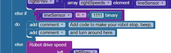
Now, instead of the large switch...case block - you can use the array values. You will add an if...do block to handle the cases that have been filled with zeros by using the leftPrev and rightPrev variables:

With shorter code, it’s easier to customize the behavior of the robot. For example, you can add an else if that looks for all four of the QTI sensors to read 1 (binary 1111, or decimal 15), and when they do, have the robot stop or turncompletely around:


Links
[1] https://learn.parallax.com/tutorials/robot/activitybot/blocklyprop-robotics-activitybot-360%C2%B0
[2] http://www.parallax.com/product/32600
[3] http://www.parallax.com/product/28108
[4] https://www.parallax.com/package/printable-tracks-for-line-following/
[5] https://learn.parallax.com/tutorials/robot/activitybot/activitybot-360-line-following-color-sensing
[6] https://solo.parallax.com/
[7] https://learn.parallax.com/sites/default/files/content/AB-Blockly/Projects/QTI/Project29631-QTI-Line-Follow.svg