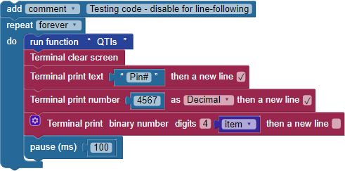
Now it is time to test the QTI sensors.
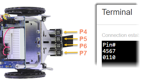
The white paper will reflect infrared light, while the black line will absorb it. Each QTI sensor emits infrared light, then looks for a reflection. When a QTI sensor is over a black line, it will return a "1" and when it is over a white surface, it will return a "0."
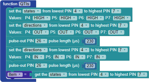
The QTIs function starts by setting the I/O pin states for all four QTI sensors to HIGH, with the direction OUT. This causes each QTI sensor to turn on its infrared LED. The pulse-out PIN 26 pulse length µs 230 block keeps the LEDs on for just a 230 microsecond flash. (We could not use the pause block here, because its shortest duration is 1 millisecond, which is 1000 microseconds).
After that, the I/O pin directions are set to IN (input) for another 230 microseconds. Each QTI sensor is looking for its infrared flash's reflection, and reports I/O pin as a zero if the reflection is seen and a 1 if it is not.
Then, the states of the four I/O pins are saved in the item variable as a four-digit binary number. So, each time through the drive routine's loop, the QTIs function updates the item variable before it gets used for navigation with the switch...case block.

Links
[1] https://solo.parallax.com/