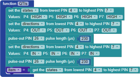
Now that you know your QTI sensors are wired properly, it's time to build the line-following code. It is long, so let's build it a few sections at a time.
You can download the code, but you should still read what's happening below so you know what sections to enable, and how it works.
Project29631-QTI-Line-Follow.svg [1]

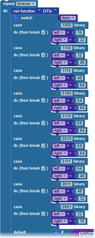
Instead of displaying the sensor states, we'll now use that 4-bit binary number to make navigation decisions. The item variable plugs into a switch...case block with nine different case options, shown in the table. The binary number determines the right and left variable values. Those variables will help adjust the robot drive values to keep your ActivityBot on the black line.
| binary | left = | right = | behavior |
|---|---|---|---|
| 1000 | 16 | 32 | pivot left |
| 1100 | 32 | 48 | sharp left |
| 1110 | 48 | 64 | left |
| 0100 | 64 | 64 | slight left |
| 0110 | 64 | 64 | forward |
| 0010 | 64 | 64 | slight right |
| 0111 | 64 | 48 | right |
| 0011 | 48 | 32 | sharp right |
| 0001 | 32 | 16 | pivot right |

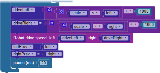
Here, the values of left and right from the switch...case block factor into the driveRight and driveLeft variables that actually set each wheel's speed. By adjusting the initial value of scale at the top of the code. you can fine-tune the robot's performance. Finally, just before the pause block, the values of left and right are saved in leftPrev and rightPrev before the loop repeats.
There are several places you can make adjustments to the code to fine-tune your robot's line-following performance. Use Save As to make copies of your project before experimenting with the adjustments.
If you take a look at the values assigned to the left and right variables for each case, you can see a pattern.

Links
[1] https://learn.parallax.com/sites/default/files/content/AB-Blockly/Projects/QTI/Project29631-QTI-Line-Follow.svg