Figures 6 & 7 - Circuit wiring for the transmitter (left) and receiver (right) boards
![]()
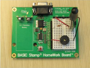
Wiring for the two boards should look something like the above figures.
' {$STAMP BS2}
' {$PBASIC 2.5}

' MultiButtonTx.bs2
' Transmit pushbutton states for multiple pushbuttons using the 433 MHz
' RF Transceiver.

TxPin     PIN     14
TR        PIN     15

Baud      CON     16468

PbStates  VAR     Byte

HIGH TR                                   ' T/R Line High - Transmit

DO
  PbStates = INA                          ' Input Pins P3..P0
  SEROUT TxPin, Baud, [PbStates]          ' Transmit all push button states
  PAUSE 10
LOOP
' {$STAMP BS2}
' {$PBASIC 2.5}

' MultiButtonRx.bs2
' Receive pushbutton states using the 433 MHz RF Transceiver and play
' tones based on what's received.

RxPin     PIN     10
TR        PIN     11

Baud      CON     16468

PbStates  VAR     Byte

LOW TR                               ' T/R Line low - receive

DO
  SERIN RxPin, Baud, [PbStates]      ' Read all Pushbutton states

  SELECT PbStates                    ' Select all Pushbutton states
    CASE %0001                       ' Pushbutton at P0 is pressed
      GOSUB Play_C                   ' Execute subroutine Play_C
    CASE %0010                       ' Pushbutton at P1 is pressed
      GOSUB Play_G                   ' Execute subroutine Play_G
    CASE %0100                       ' Pushbutton at P2 is pressed
      GOSUB Play_A                   ' Execute subroutine Play_A
  ENDSELECT
LOOP

Play_C:
  FREQOUT 4, 500, 2093
  RETURN

Play_G:
  FREQOUT 4, 500, 3136
  RETURN

Play_A:
  FREQOUT 4, 500, 3520
  RETURN
The program MultiButtonTx.bs2 utilizes the SEROUT command to transmit the states of the pushbuttons to the receiver board. The INA argument is what’s called the “Nibble Name” which monitors the states of all devices connected to pins 0-3. Recall that the command DEBUG ? IN3 prints “IN3 = 1” or “IN3 = 0” in the Debug Terminal depending on whether the pushbutton is pressed. So when the command INA is called, it’s really the same as calling IN0, IN1, IN2, IN3. Then, when SEROUT TxPin, Baud, [PbStates] is called; it then sends the state of each pushbutton connected to P0, P1, P2, and P3 to the Parallax 433 MHz RF Transceiver.
The program MultiButtonRx.bs2 utilizes the SEROUT command to receive the states of the pushbuttons from the transmitter board. However, it’s also a bit more complicated, since once the states are received, the program then has to decide what to do. In order to sort each pushbutton state, the program uses a SELECT…CASE command. Once SELECT PbStates is called, the received values of each pushbutton state are loaded into RAM as a byte. However, there are four states that are received.
So how does the BASIC Stamp 2 store these values? The simplest way to analyze how this is done is to read each byte in binary. Since PbStates was defined as a Byte, there are four “spots” for the state of each pushbutton. Remember, binary only stores values as 0’s or 1’s, and 0 is usually denoted as low and 1 as high. So if we assign each “spot” to one pushbutton, the CASE command can be used to execute subroutines based on PbStates’s binary value. The table below shows examples of how the BASIC Stamp will read each pushbutton state based on the binary value it has received. Our program is checking the states of the first three pushbuttons, but the INA command can check the first three pins, if desired.
|
Binary Value |
Pushbutton Reaction |
|
%0000 |
No PB Pressed |
|
%0001 |
PB connected to P0 pressed |
|
%0010 |
PB connected to P1 pressed |
|
%0100 |
PB connected to P2 pressed |
|
%0011 |
PB connected to P0 & P1 pressed |
|
%0111 |
PB connected to P0, P1 & P2 pressed |
Therefore, by knowing the binary equivalent of each pushbutton being pressed; the CASE command can be used to compare each binary condition to PbStates and execute a subroutine based on that value. In this program, depending on which pushbutton is pressed, a different note will play.
