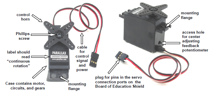
From the robot navigation standpoint, continuous rotation servos offer a great combination of simplicity, usefulness and low price. The Parallax continuous rotation servos are the motors that will make the BOE Shield-Bot’s wheels turn, under Arduino control.
In this activity, you will connect your servos to the Board of Education Shield’s servo ports, which will connect them to supply voltage, ground, and a signal pin. You will also connect a battery supply to your Arduino because, under certain conditions, servos can end up demanding more current than a USB supply is designed to deliver.
Standard Servos vs. Continuous Rotation Servos
Standard servos are designed to receive electronic signals that tell them what position to hold. These servos control the positions of radio controlled airplane flaps, boat rudders, and car steering. Continuous rotation servos receive the same electronic signals, but instead turn at certain speeds and directions. Continuous rotation servos are handy for controlling wheels and pulleys.
Servo Control Horn, 4-point Star vs. Round
It doesn’t make a difference. So long as it is labeled “continuous rotation” it’s the servo for your BOE Shield-Bot. You’ll remove the control horn and replace it with a wheel.
Leave the LED circuits from the last activity on your board. They will be used later to monitor the signals the Arduino sends to the servos to control their motion.
(2) Parallax continuous rotation servos
BOE Shield with built and tested LED indicator circuits from the previous activity
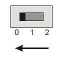
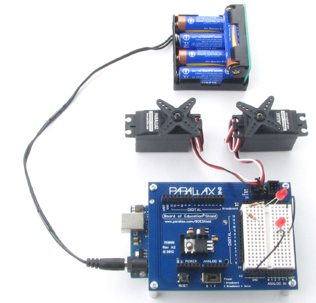
Between the servo headers on the BOE Shield is a jumper that connects the servo power supply to either Vin or 5V. To move it, pull it upwards and off the pair of pins it covers, then push it onto the pair of pins you want it to rest on. The BOE Shield-Bot’s battery pack will supply 7.5 V. Since the servos are rated for 4–6 V, we want to make sure the jumper is set to 5V. Also, a steady 5 V voltage supply will support a consistent servo speed, and more accurate navigation, than voltage that varies as batteries discharge.
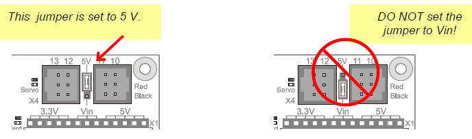
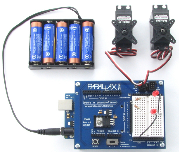
The picture below shows the schematic of the circuit you create by plugging the servos into ports 13 and 12 on the BOE Shield. Pay careful attention to wire color as you plug in the cables: the black wire should be at the bottom, and the white one should be at the top.
To properly power the servos, you’ll need to switch to an external battery pack now. When servos make sudden direction changes or push against resistance to rotation, they can draw more current than a USB port is designed to supply. Also, it would be no fun for the BOE Shield-Bot to be tethered to the computer forever! So, from here on out we’ll be using an external battery pack with five 1.5 V AA batteries. This will supply your system with 7.5 V and plenty of current for the voltage regulators and servos. From here forward, remember two things:
Rechargeable Options
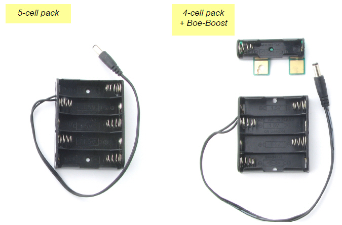
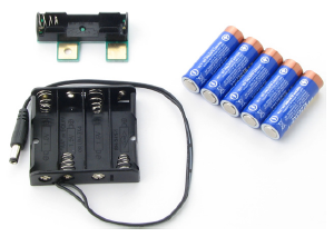
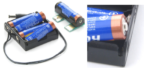
The thrifty Boe-Boost (#30078) allows you to add another cell in series with a 4-cell or 5-cell pack. Adding a 6th 1.2 V AA rechargeable cell to a 5-cell pack will supply 6 x 1.2 = 7.2 V.
The Li-ion Boe-Bot Power Pack-Charger (#28988) combines a lithium-ion battery pack and recharger in one board that you can mount under your Shield-Bot.
CAUTION: AC powered DC supplies are not recommended for the BOE Shield-Bot.
Some DC supplies provide much higher voltage than their rating. The BOE Shield-bot is designed for use with a 7.2–7.5 V battery supply. It will work with higher supply voltages at low loads, but the servo loads can heat up the regulator until it shuts off to protect itself.
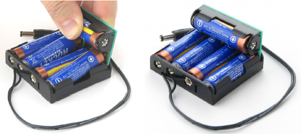
(5) AA alkaline batteries
(1) 5-cell battery pack
(1) Boe-Boost
(1) 4-cell battery pack
(5) AA alkaline batteries


Links
[1] https://learn.parallax.com/184
[2] https://learn.parallax.com/185