Leave the LED circuits from the last activity on your board. They will be used later to monitor the signals the Arduino sends to the servos to control their motion.
(2) Parallax continuous rotation servos
BOE Shield with built and tested LED indicator circuits from the previous activity
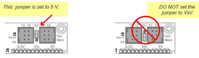
Between the servo headers on the BOE Shield is a jumper that connects the servo power supply to either Vin or 5V. To move it, pull it upwards and off the pair of pins it covers, then push it onto the pair of pins you want it to rest on. The BOE Shield-Bot’s battery pack will supply 7.5 V. Since the servos are rated for 4–6 V, we want to make sure the jumper is set to 5V. Also, a steady 5 V voltage supply will support a consistent servo speed, and more accurate navigation, than voltage that varies as batteries discharge.
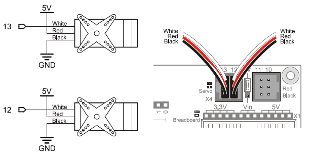
The picture below shows the schematic of the circuit you create by plugging the servos into ports 13 and 12 on the BOE Shield. Pay careful attention to wire color as you plug in the cables: the black wire should be at the bottom, and the white one should be at the top.