There’s one last thing to do before assembling your BOE Shield-Bot, and that’s testing the servos. In this activity, you will run sketches that make the servos turn at different speeds and directions. This is an example of subsystem testing—a good habit to develop.
Subsystem testing is the practice of testing the individual components before they go into the larger device. It’s a valuable strategy that can help you win robotics contests. It’s also an essential skill used by engineers to develop everything from toys, cars, and video games to space shuttles and Mars roving robots. Especially in more complex devices, it can become nearly impossible to figure out a problem if the individual components haven’t been tested beforehand. In aerospace projects, for example, disassembling a prototype to fix a problem can cost hundreds of thousands, or even millions, of dollars. In those kinds of projects, subsystem testing is rigorous and thorough.
This timing diagram shows how a Parallax continuous rotation servo turns full speed clockwise when you send it 1.3 ms pulses. Full speed typically falls in the 50 to 60 RPM range.
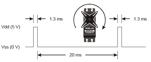
What’s RPM? Revolutions Per Minute—the number of full rotations turned in one minute.
What’s a pulse train? Just as a railroad train is a series of cars, a pulse train is a series of pulses (brief high signals).
/*
 Robotics with the BOE Shield – LeftServoClockwise
 Generate a servo full speed clockwise signal on digital pin 13.
 */

#include <Servo.h>                           // Include servo library

Servo servoLeft;                             // Declare left servo

void setup()                                 // Built in initialization block
{
  servoLeft.attach(13);                      // Attach left signal to pin 13
  servoLeft.writeMicroseconds(1300);         // 1.3 ms full speed clockwise
}

void loop()                                  // Main loop auto-repeats
{                                            // Empty, nothing needs repeating
}
/*
 Robotics with the BOE Shield – RightServoClockwise
 Generate a servo full speed clockwise signal on digital pin 12.
 */

#include <Servo.h>                           // Include servo library

Servo servoRight;                            // Declare left servo

void setup()                                 // Built in initialization block
{
  servoRight.attach(12);                     // Attach left signal to pin 12
  servoRight.writeMicroseconds(1300);        // 1.3 ms full speed clockwise
}

void loop()                                  // Main loop auto-repeats
{                                            // Empty, nothing needs repeating
}
For BOE Shield-Bot navigation, we need to control both servos at once.
 /*
 Robotics with the BOE Shield – ServosOppositeDirections
 Generate a servo full speed counterclockwise signal with pin 13 and
 full speed clockwise signal with pin 12.
 */

#include <Servo.h>                           // Include servo library

Servo servoLeft;                             // Declare left servo signal
Servo servoRight;                            // Declare right servo signal

void setup()                                 // Built in initialization block
{
  servoLeft.attach(13);                      // Attach left signal to pin 13
  servoRight.attach(12);                     // Attach right signal to pin 12

  servoLeft.writeMicroseconds(1700);         // 1.7 ms -> counterclockwise
  servoRight.writeMicroseconds(1300);        // 1.3 ms -> clockwise
}

void loop()                                  // Main loop auto-repeats
{                                            // Empty, nothing needs repeating
}
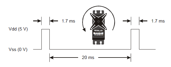
This opposite-direction control will be important soon. Think about it: when the servos are mounted on either side of a chassis, one will have to rotate clockwise while the other rotates counterclockwise to make the BOE Shield-Bot roll in a straight line. Does that seem odd? If you can’t picture it, try this:
Pulse Width Modulation
Adjusting the property of a signal to carry information is called modulation. We’ve discovered that servo control signals are a series of high pulses separated by low resting states. How long the high pulse lasts—how wide the high pulse looks in a timing diagram—determines the speed and direction that the servo turns. That adjustable pulse width carries the servo setting information. Therefore, we can say that servos are controlled with pulse width modulation.
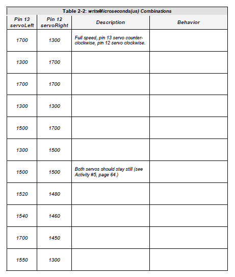
Different combinations of writeMicroseconds us parameters will be used repeatedly for programming your BOE Shield-Bot’s motion. By testing several possible combinations and filling in the Description column of Table 2‑2, you will become familiar with them and build a reference for yourself. You’ll fill in the Behavior column later on, when you see how the combinations make your assembled BOE Shield-Bot move.
It’s easy to control how long the servos run when using the Servo library. Once set, a servo will maintain its motion until it receives a new setting. So, to make a servo run for a certain length of time, all you have to do is insert a delay after each setting.
/*
 Robotics with the BOE Shield – ServoRunTimes
 Generate a servo full speed counterclockwise signal with pin 13 and
 full speed clockwise signal with pin 12.
 */

#include <Servo.h>                           // Include servo library

Servo servoLeft;                             // Declare left servo signal
Servo servoRight;                            // Declare right servo signal

void setup()                                 // Built in initialization block
{
  servoLeft.attach(13);                      // Attach left signal to pin 13
  servoRight.attach(12);                     // Attach right signal to pin 12

  servoLeft.writeMicroseconds(1300);         // Pin 13 clockwise
  servoRight.writeMicroseconds(1300);        // Pin 12 clockwise
  delay(3000);                               // ..for 3 seconds
  servoLeft.writeMicroseconds(1700);         // Pin 13 counterclockwise
  servoRight.writeMicroseconds(1700);        // Pin 12 counterclockwise
  delay(3000);                               // ..for 3 seconds
  servoLeft.writeMicroseconds(1500);         // Pin 13 stay still
  servoRight.writeMicroseconds(1500);        // Pin 12 stay still
}

void loop()                                  // Main loop auto-repeats
{                                            // Empty, nothing needs repeating
}
