For BOE Shield-Bot navigation, we need to control both servos at once.
 /*
 Robotics with the BOE Shield – ServosOppositeDirections
 Generate a servo full speed counterclockwise signal with pin 13 and
 full speed clockwise signal with pin 12.
 */

#include <Servo.h>                           // Include servo library

Servo servoLeft;                             // Declare left servo signal
Servo servoRight;                            // Declare right servo signal

void setup()                                 // Built in initialization block
{
  servoLeft.attach(13);                      // Attach left signal to pin 13
  servoRight.attach(12);                     // Attach right signal to pin 12

  servoLeft.writeMicroseconds(1700);         // 1.7 ms -> counterclockwise
  servoRight.writeMicroseconds(1300);        // 1.3 ms -> clockwise
}

void loop()                                  // Main loop auto-repeats
{                                            // Empty, nothing needs repeating
}
This opposite-direction control will be important soon. Think about it: when the servos are mounted on either side of a chassis, one will have to rotate clockwise while the other rotates counterclockwise to make the BOE Shield-Bot roll in a straight line. Does that seem odd? If you can’t picture it, try this:
Pulse Width Modulation
Adjusting the property of a signal to carry information is called modulation. We’ve discovered that servo control signals are a series of high pulses separated by low resting states. How long the high pulse lasts—how wide the high pulse looks in a timing diagram—determines the speed and direction that the servo turns. That adjustable pulse width carries the servo setting information. Therefore, we can say that servos are controlled with pulse width modulation.
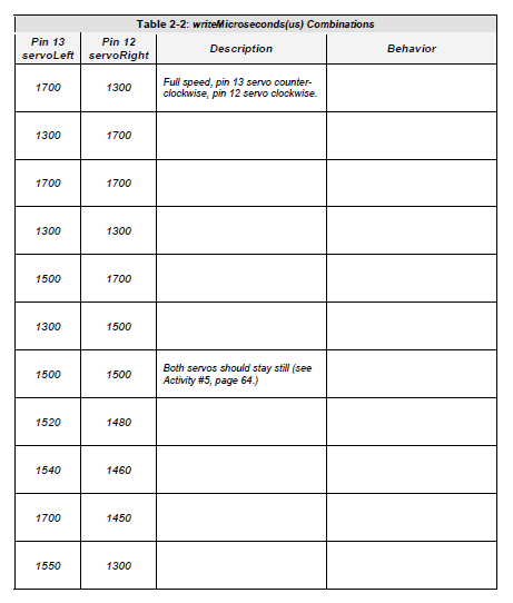
Different combinations of writeMicroseconds us parameters will be used repeatedly for programming your BOE Shield-Bot’s motion. By testing several possible combinations and filling in the Description column of Table 2‑2, you will become familiar with them and build a reference for yourself. You’ll fill in the Behavior column later on, when you see how the combinations make your assembled BOE Shield-Bot move.