This chapter contains instructions for building and testing your BOE Shield-Bot. It’s especially important to complete the testing portion before moving on to the next chapter. By doing so, you can help avoid a number of common mistakes that could otherwise lead to mystifying BOE Shield-Bot behavior. Here is a summary of what you will do:

Code Update Notice
The Chapter 3 Arduino Code was updated on 11/15/2012. See the notice on this page [2] for details.
This activity will guide you through assembling the BOE Shield-Bot, step by step. In each step, you will gather a few of the parts, and then assemble them so that they match the pictures. Each picture has instructions that go with it; make sure to follow them carefully.
All of the tools needed are common and can be found in most households and school shops. They can also be purchased at local hardware stores. The Parallax screwdriver is included in the Robotics Shield Kit, and the other two are optional but handy to have.
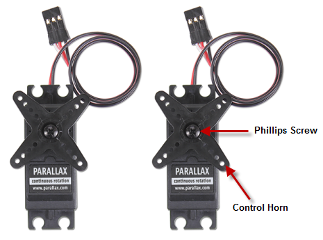
(1) screwdriver, Phillips #1
(1) 1/4″ combination wrench (optional but handy)
(1) needle-nose pliers (optional)

(1) robot chassis
(2) 1″ standoffs (removed from BOE Shield)
(2) pan-head screws, 1/4″ 4-40 (removed from BOE Shield)
(1) rubber grommet, 13/32″

(2) Parallax continuous rotation servos, previously centered
STOP! Before taking the next step, you must have completed these activities: Chapter 2, Activity 4: Connect Servo Motors and Batteries [3], and Chapter 2, Activity 5: Centering the Servos [4].
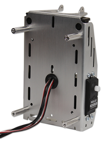
BOE Shield-Bot Chassis, partially assembled.
(2) Parallax continuous rotation servos
(8) pan Head Screws, 3/8″ 4-40
(8) nuts, 4-40 or lock nuts
1/4" combination wrench (optional, needed for locknuts only)
masking tape
pen
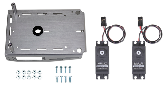
Note: You can choose to use either hex nuts or locknuts to mount your servos, both are provided. Locknuts provide a tighter connection, but if your robots need frequent repair or part replacements then hex nuts are the easiest to remove and reattach quickly.
(2) Nylon flat-head slotted screws, 3/8″ 4-40
(2) 1" standoffs (removed from BOE Shield previously)
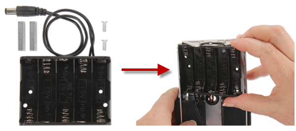
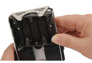
(1) 5-cell battery pack with 2.1 mm center-positive plug
(1) 1/16″ cotter pin
(1) tail wheel ball
(2) O-ring tires
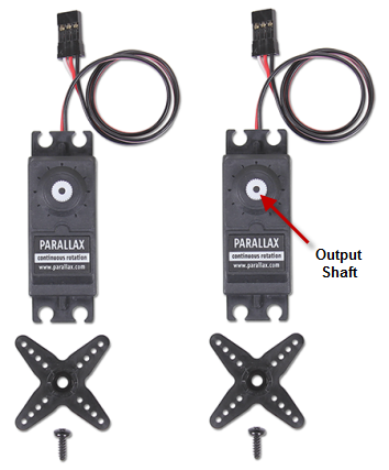
(2) plastic machined wheels
(2) screws saved when removing the servo horns

The robot’s tail wheel is merely a plastic ball with a hole through the center. A cotter pin holds it to the chassis and functions as an axle for the wheel.

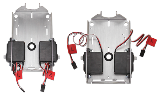
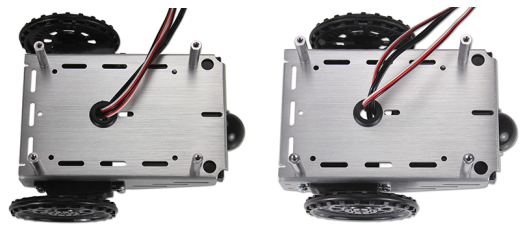
When you are done, your completed chassis will look like one of the pictures below.
Left: "Outside-forward" servos
Right: "Inside-backward" servos
(4) pan-head screws, 1/4″ 4-40
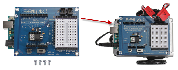
(1) Board of Education Shield mounted to your Arduino module and secured with standoffs [5].
Using Different Pins for the Servos
The Arduino toggles Pin 13 briefly upon startup or reset. If this causes problems for a particular application, you can use Pins 11 and 12 instead of 12 and 13. Be sure to adjust your code accordingly.
If you are building the BOE Shield-Bot to use with ROBOTC instead of for this tutorial, follow these instructions for using different servo ports [6].
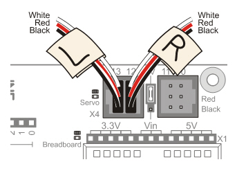
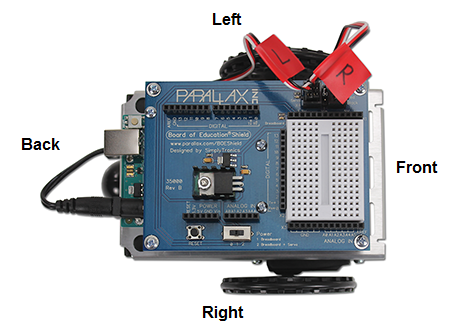
In this activity, you will test to make sure that the electrical connections between your board and the servos are correct. The picture below shows your BOE Shield-Bot’s front, back, left, and right. We need to make sure that the right-side servo turns when it receives pulses from pin 12 and that the left-side servo turns when it receives pulses from pin 13.
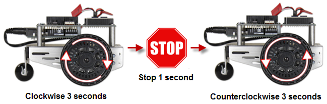
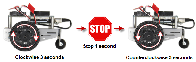
The next example sketch will test the servo connected to the right wheel, shown below. The sketch will make this wheel turn clockwise for three seconds, then stop for one second, then turn counterclockwise for three seconds.
/*
 * Robotics with the BOE Shield - RightServoTest
 * Right servo turns clockwise three seconds, stops 1 second, then
 * counterclockwise three seconds.
 */

#include <Servo.h>                           // Include servo library

Servo servoRight;                            // Declare right servo

void setup()                                 // Built in initialization block
{
  servoRight.attach(12);                     // Attach right signal to pin 12

  servoRight.writeMicroseconds(1300);        // Right wheel clockwise
  delay(3000);                               // ...for 3 seconds

  servoRight.writeMicroseconds(1500);        // Stay still
  delay(1000);                               // ...for 3 seconds

  servoRight.writeMicroseconds(1700);        // Right wheel counterclockwise
  delay(3000);                               // ...for 3 seconds

  servoRight.writeMicroseconds(1500);        // Right wheel counterclockwise

}

void loop()                                  // Main loop auto-repeats
{                                            // Empty, nothing needs repeating
}
Now, it’s time to run the same test on the left wheel as shown below. This involves modifying the RightServoTest sketch.
Here is a list of some common symptoms and how to fix them.
The first step is to double check your sketch and make sure all the code is correct.
The servo doesn’t turn at all.
The left servo turns when the right one is supposed to.
This means that the servos are swapped. The servo that’s connected to pin 12 should be connected to pin 13, and the servo that’s connected to pin 13 should be connected to pin 12.
The wheel does not fully stop; it still turns slowly.
If the wheel keeps turning slowly after the clockwise, stop, counterclockwise sequence, it means that the servo may not be exactly centered. There are two ways to fix this:
The wheel never stops, it just keeps turning rapidly.
If you are sure the code in your sketch is correct, it probably means your servo is not properly centered.
In this activity, we’ll build a small noise-making circuit on the BOE Shield’s prototyping area that will generate a tone if the robot’s batteries run too low.
When the voltage supply drops below the level a device needs to function properly, it’s called brownout. The device (your Arduino) typically shuts down until the supply voltage returns to normal. Then, it will restart whatever sketch it was running.
Brownouts typically happen when batteries are already running low, and the servos suddenly demand more power. For example, if the BOE Shield-Bot changes from full speed forward to full speed backward, the servos have to do extra work to stop the servos and then go the other direction. For this, they need more current, and when they try to pull that current from tired batteries, the output voltage dips enough to cause brownout.
Now, imagine your BOE Shield-Bot is navigating through a routine, and suddenly it stops for a moment and then goes in a completely unexpected direction. How will you know if it is a mistake in your code, or if it’s a brownout? One simple, effective solution is to add a speaker to your BOE Shield-Bot and make it play a “start” tone at the beginning of every sketch. That way, if your BOE Shield-Bot has a brownout while it’s navigating, you’ll know right away because it’ll play the start tone.
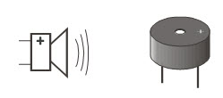
We’ll use a device called a piezoelectric speaker (piezospeaker) that can make different tones depending on the frequency of high/low signals it receives from the Arduino. The schematic symbol and part drawing are shown below.
Frequency is the measurement of how often something occurs in a given amount of time.
A piezoelectric element is a crystal that changes shape slightly when voltage is applied to it. Applying high and low voltages at a rapid rate causes the crystal to rapidly change shape. The resulting vibration in turn vibrates the air around it, and this is what our ear detects as a tone. Every rate of vibration makes a different tone.
Piezoelectric elements have many uses. When force is applied to a piezoelectric element, it can create voltage. Some piezoelectric elements have a frequency at which they naturally vibrate. These can be used to create voltages at frequencies that function as the clock oscillator for many computers and microcontrollers.
(1) piezospeaker (just peel off the “Remove the seal after washing” sticker if it has one)
(misc.) jumper wires
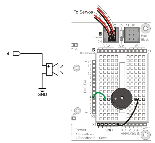
The picture below shows a wiring diagram for adding a piezospeaker to the breadboard.
Always disconnect power before building or modifying circuits!
Set the Power switch to 0.
Unplug the battery pack.
Unplug the programming cable.
The next example sketch tests the piezospeaker using calls to the Arduino’s tone function. True to its name, this function send signals to speakers to make them play tones.
There are two options for calling the tone function. One allows you to specify the pin and frequency (pitch) of the tone. The other allows you to specify pin, frequency, and duration (in milliseconds). We’ll be using the second option since we don’t need the tone to go on indefinitely.
tone(pin, frequency) tone(pin, frequency, duration)
This piezospeaker is designed to play 4.5 kHz tones for smoke alarms, but it can also play a variety of audible tones and usually sounds best in the 1 kHz to 3.5 kHz range. The start-alert tone we’ll use is:
tone(4, 3000, 1000);
delay(1000);
That will make pin 4 send a series of high/low signals repeating at 3 kHz (3000 times per second). The tone will last for 1000 ms, which is 1 second. The tone function continues in the background while the sketch moves on to the next command. We don’t want the servos to start moving until the tone is done playing, so the tone command is followed by delay(1000) to let the tone finish before the sketch can move on to servo control.
Frequency can be measured in hertz (Hz) which is the number of times a signal repeats itself in one second. The human ear is able to detect frequencies in a range from very low pitch (20 Hz) to very high pitch (20 kHz or 20,000 Hz). One kilohertz is one-thousand-times-per-second, abbreviated 1 kHz.
This example sketch makes a beep when it starts running, then it goes on to send Serial Monitor messages every half-second. These messages will continue indefinitely because they are in the loop function. If the power to the Arduino is interrupted, the sketch will start at the beginning again, and you will hear the beep.
/*
 * Robotics with the BOE Shield - StartResetIndicator
 * Test the piezospeaker circuit.
 */

void setup()                                 // Built in initialization block
{
  Serial.begin(9600);
  Serial.println("Beep!");

  tone(4, 3000, 1000);                       // Play tone for 1 second
  delay(1000);                               // Delay to finish tone
}

void loop()                                  // Main loop auto-repeats
{
  Serial.println("Waiting for reset...");
  delay(1000);
}
StartResetIndicator begins by displaying the message “Beep!” in the Serial Monitor. Then, immediately after printing the message, the tone function plays a 3 kHz tone on the piezoelectric speaker for 1 second. Because the instructions are executed so rapidly by the Arduino, it should seem as though the message is displayed at the same instant the piezospeaker starts to play the tone.
When the tone is done, the sketch enters the loop function, which displays the same “Waiting for reset…” message over and over again. Each time the reset button on the BOE Shield is pressed or the power is disconnected and reconnected, the sketch starts over again with the “Beep!” message and the 3 kHz tone.
Sketch Update Notice!!!
The sketch StartResetIndicator was updated on 11/16/2012. On the Arduino Mega 2650, the upload hangs with the original code listing. The offending command was:
Serial.println("Beep!!!");
It turns out that having more than one exclamation point in a row in a serial string causes this problem in the Mega 2650. From this point forward, we will find another way to express our enthusiasm in serial strings. - Editor.
We'll use tone at the beginning of every example sketch from here onward. So, it’s a good idea to get in the habit of putting tone and delay statements at the beginning of every sketch’s setup function.
This graph shows pulse time vs. servo speed. The graph’s horizontal axis shows the pulse width in microseconds (µs), and the vertical axis shows the servo’s response in RPM. Clockwise rotation is shown as negative, and counterclockwise is positive. This particular servo’s graph, which can also be called a transfer curve, ranges from about -48 to +48 RPM over the range of test pulse widths from 1300 to 1700 µs. A transfer curve graph of your servos would be similar.

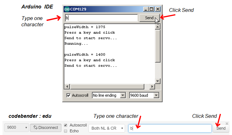
With this sketch, you can check servo RPM speed (and direction) for pulse values from 1375 µs to 1625 µs in steps of 25 μs. These speed measurements will help make it clear how servo control pulse durations in the 1400 to 1600 µs range control servo speed. This sketch starts by displaying the pulse duration that it’s ready to send as a servo control signal. Then, it waits for you to send the Arduino a character with the Serial Monitor before it runs the servo. It runs the servo for six seconds, and during that time you can count the number of full turns the wheel makes. After that, the for loop repeats itself, and increases the pulse duration by 25 for the next test.
/*
 Robotics with the BOE Shield – TestServoSpeed
 Send a character from the Serial Monitor to the Arduino to make it run the
 left servo for 6 seconds.  Starts with 1375 us pulses and increases by
 25 us with each repetition, up to 1625 us.  This sketch is useful for
 graphing speed vs. pulse width.
 */

#include <Servo.h>                           // Include servo library

Servo servoLeft;                             // Declare left servo signal
Servo servoRight;                            // Declare right servo signal

void setup()                                 // Built in initialization block
{
  tone(4, 3000, 1000);                       // Play tone for 1 second
  delay(1000);                               // Delay to finish tone

  Serial.begin(9600);                        // Set data rate to 9600 bps
  servoLeft.attach(13);                      // Attach left signal to P13
}

void loop()                                  // Main loop auto-repeats
{

  // Loop counts with pulseWidth from 1375 to 1625 in increments of 25.

  for(int pulseWidth = 1375; pulseWidth <= 1625; pulseWidth += 25)
  {
    Serial.print("pulseWidth = ");           // Display pulseWidth value
    Serial.println(pulseWidth);
    Serial.println("Press a key and click"); // User prompt
    Serial.println("Send to start servo...");

    while(Serial.available() == 0);          // Wait for character
    Serial.read();                           // Clear character

    Serial.println("Running...");
    servoLeft.writeMicroseconds(pulseWidth); // Pin 13 servo speed = pulse
    delay(6000);                             // ..for 6 seconds
    servoLeft.writeMicroseconds(1500);       // Pin 13 servo speed = stop
  }
}
The sketch TestServoSpeed increments the value of a variable named pulseWidth by 25 each time through a for loop.
  // Loop counts with pulseWidth from 1375 to 1625 in increments of 25.

  for(int pulseWidth = 1375; pulseWidth <= 1625; pulseWidth += 25)
With each repetition of the for loop, it displays the value of the next pulse width that it will send to the pin 13 servo, along with a user prompt.
    Serial.print("pulseWidth = ");           // Display pulseWidth value
    Serial.println(pulseWidth);
    Serial.println("Press a key and click"); // User prompt
    Serial.println("Send to start servo...");
After Serial.begin in the setup loop, the Arduino sets aside some memory for characters coming in from the Serial Monitor. This memory is typically called a serial buffer, and that’s where ASCII values from the Serial Monitor are stored. Each time you use Serial.read to get a character from the buffer, the Arduino subtracts 1 from the number of characters waiting in the buffer.
A call to Serial.available will tell you how many characters are in the buffer. This sketch uses while(Serial.available() = = 0) to wait until the Serial Monitor sends a character. Before moving on to run the servos, it uses Serial.read( ) to remove the character from the buffer. The sketch could have used int myVar = Serial.read( ) to copy the character to a variable. Since the code isn’t using the character’s value to make decisions, it just calls Serial.read, but doesn’t copy the result anywhere. The important part is that it needs to clear the buffer so that Serial.available( ) returns zero next time through the loop.
while(Serial.available() == 0);      // Wait for character
Serial.read();                       // Clear character
Where is the while loop’s code block?
The C language allows the while loop to use an empty code block, in this case to wait there until it receives a character. When you type a character into the Serial Monitor, Serial.available returns 1 instead of 0, so the while loop lets the sketch move on to the next statement. Serial.read removes that character you typed from the Arduino’s serial buffer to make sure that Serial.available returns 0 next time through the loop. You could have typed this empty while loop other ways:
while(Serial.available() == 0) {}
...or:
while(Serial.available() == 0) {}; .
After the Arduino receives a character from the keyboard, it displays the “Running…” message and then makes the servo turn for 6 seconds. Remember that the for loop this code is in starts the pulseWidth variable at 1375 and adds 25 to it with each repetition. So, the first time through the loop, servoLeft is 1375, the second time through it’s 1400, and so on all the way up to 1625.
Each time through the loop, servoLeft.writeMicroseconds(pulseWidth) uses the value that pulseWidth stores to set servo speed. That’s how it updates the servo’s speed each time you send a character to the Arduino with the Serial Monitor.
Serial.println("Running...");
servoLeft.writeMicroseconds(pulseWidth); // Pin 13 speed=pulse
delay(6000);                             // ..for 6 seconds
servoLeft.writeMicroseconds(1500);       // Pin 13 speed=stop
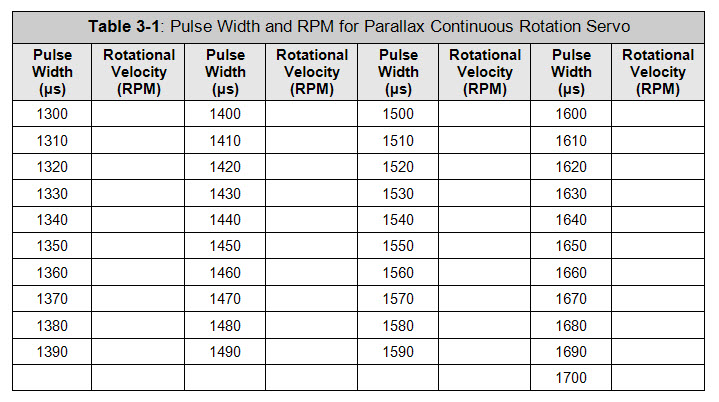
You can use the table below to record the data for your own transfer curve. The TestServoSpeed sketch’s loop can be modified to test every value in the table, or every other value to save time.
for(int pulseWidth=1375; pulseWidth <= 1625; pulseWidth += 25)
…to:
for(int pulseWidth=1300; pulseWidth <= 1700; pulseWidth += 20)
This chapter covered BOE Shield-Bot assembly and testing. Assembly involved both mechanical construction and circuit-building, and testing used some new programming concepts. Here are the highlights:
Hardware Setup
Electronics
Programming
Engineering Skills
/*
 Robotics with the BOE Shield – Chapter 3, Project 1
*/

#include <Servo.h>                           // Include servo library

Servo servoLeft;                             // Declare left servo signal
Servo servoRight;                            // Declare right servo signal

void setup()                                 // Built in initialization block
{
  tone(4, 3000, 1000);                       // Play tone for 1 second
  delay(1000);                               // Delay to finish tone

  Serial.begin(9600);                        // Set data rate to 9600 bps
  servoLeft.attach(13);                      // Attach left signal to P13
}

void loop()                                  // Main loop auto-repeats
{

  // Loop counts with pulseWidth from 1375 to 1625 in increments of 25.

  for(int pulseWidth = 1375; pulseWidth <= 1625; pulseWidth += 25)
  {
    Serial.print("pulseWidth = ");           // Display pulseWidth value
    Serial.println(pulseWidth);
    Serial.println("Press a key and click"); // User prompt
    Serial.println("Send to start servo...");

    while(Serial.available() == 0);          // Wait for character
    Serial.read();                           // Clear character

    Serial.println("Running...");
    servoLeft.writeMicroseconds(pulseWidth);   // Pin 13 servo speed = pulse
    delay(6000);                               // ..for 6 seconds
    servoLeft.writeMicroseconds(1500);         // Pin 13 servo speed = stop
    tone(4, 4000, 75);                         // Test complete
  }
}
servoRight.writeMicroseconds(1500 + (1500 – pulseWidth))
Remember to add a servoRight.writeMicroseconds(1500) after the 6-second run time.
/*
 Robotics with the BOE Shield – Chapter 3, Project 2
*/

#include <Servo.h>                           // Include servo library

Servo servoLeft;                             // Declare left servo signal
Servo servoRight;                            // Declare right servo signal

void setup()                                 // Built in initialization block
{
  tone(4, 3000, 1000);                       // Play tone for 1 second
  delay(1000);                               // Delay to finish tone

  Serial.begin(9600);                        // Set data rate to 9600 bps
  servoLeft.attach(13);                      // Attach left signal to P13
  servoRight.attach(12);                     // Attach right signal to P12
}

void loop()                                  // Main loop auto-repeats
{

  // Loop counts with pulseWidth from 1375 to 1625 in increments of 25.

  for(int pulseWidth = 1375; pulseWidth <= 1625; pulseWidth += 25)
  {
    Serial.print("pulseWidth = ");           // Display pulseWidth value
    Serial.println(pulseWidth);
    Serial.println("Press a key and click"); // User prompt
    Serial.println("Send to start servo...");

    while(Serial.available() == 0);          // Wait for character
    Serial.read();                           // Clear character

    Serial.println("Running...");
    servoLeft.writeMicroseconds(pulseWidth);   // Pin 13 servo speed = pulse
    // Pin 12 servo opposite direction of pin 13 servo.
    servoRight.writeMicroseconds(1500 + (1500 - pulseWidth));
    delay(6000);                               // ..for 6 seconds
    servoLeft.writeMicroseconds(1500);         // Pin 13 servo speed = stop
    servoRight.writeMicroseconds(1500);        // Pin 12 servo speed = stop
    tone(4, 4000, 75);                         // Test complete
  }
}

Links
[1] https://learn.parallax.com/sites/default/files/content/shield/robo_ch3/RoboticsBOEShield_Ch3_2012-11-16.zip
[2] https://learn.parallax.com/tutorials/robot/shield-bot/robotics-board-education-shield-arduino/chapter-3-assemble-and-test-6
[3] https://learn.parallax.com/180
[4] https://learn.parallax.com/185
[5] https://learn.parallax.com/170
[6] http://learn.parallax.com/node/359
[7] https://learn.parallax.com/202
[8] https://learn.parallax.com/203
[9] https://learn.parallax.com/199