Now it is time to test the QTI sensors using the micro:bot LEDs for visual feedback.
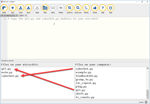
As shown with the Mu editor you will see the modules appear on your micro:bit after successfully copying each one over.
# QTI_Display_Detections.py
# Test program uses micro:bit LEDs to display QTI states

from cyberbot import *                      # import modules
from qti import *
from intbits import *                       # cyberbot library 0.7.0 or later

bot(22).tone(500, 1000)                     # start beep

while True:                                 # main loop

    pattern = qti(7, 4).read()              # store 1/0 detect states in pattern

    for x in range(0,4):                    # loop 4x count LED columns with x
        z = bit.get(pattern, x)             # get 1s or 0s from pattern
        for y in range (0,5):               # use y to visit each row
            display.set_pixel(x, y, z*9)    # LED on 9 or off 0 in x-col y-row
If the sensors don't see the line, try the following adjustments:
This statement copies line detection information for all four QTI sensors into a single int variable:
pattern = qti(7, 4).read()
The qti(7, 4).read() call returns the states of QTI sensors connected to sockets P7 through P4. These states are stored as binary 1 and 0 digits in the int variable named pattern. If a digit is 1, it indicates a black or non-reflective surface. If it’s 0, it indicates a white or reflective surface.
Suppose the two middle QTI sensors are over a black line so that they are both 1’s. The pattern variable’s value would be 0b0110.
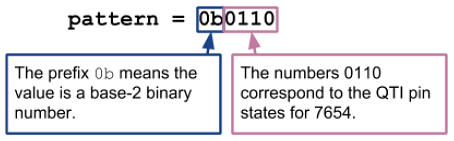
After storing the QTI states, a loop uses the qti module’s check_bit method to successively check binary digits in pattern and store them in the z variable. The for x in range(0, 4) loop starts at the rightmost binary digit in pattern and works its way left by increasing the x variable’s value with each repetition: 0, 1, 2, 3. As an argument in the check_bit method, x selects which binary digit in pattern to return, and that binary 1/0 return value gets stored in the z int variable.
    for x in range(0,4):                 # loop 4 times through qti value
        z = qti.check_bit(pattern, x)    # qti.check_bit is 1 or 0 for each x index
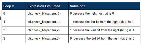
With the example 0b0110, this is how z evaluates at each loop repetition:
A nested loop turns all micro:bit LEDs in certain columns on or off to indicate which QTIs are over a black or white surface:
        for y in range (0,5):            # set each x column of LEDs on when z is 1
            display.set_pixel(x, y, z*9)
The third argument in display.set_pixel(x, y, z*9) sets the brightness (from 0 to 9). If z is 0, then the brightness is z * 9 = 0 (off). If z is 1 then the brightness of z * 9 = 9 (max brightness). Instead of just one LED, the for y in range (0,5) loop makes display.set_pixel set all LEDs in a given x column to on or off in response to a z value of 1 or 0. For more info on display, try the examples in the LED Matrix [2] tutorial.

Links
[1] http://learn.parallax.com/tutorials/robot/cyberbot/add-modules-your-microbit
[2] http://learn.parallax.com/tutorials/robot/cyberbot/writing-microbit-programs/led-matrix