Remember subsystem testing? First, we’ll build the whiskers circuits and write code to check their input states before using them in navigation sketches.
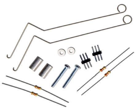
(2) whisker wires
(2) 7/8″ pan head 4-40 Phillips screws
(2) ½″ round spacer
(2) nylon washers, size #4
(2) 3-pin m/m headers
(2) resistors, 220 Ω (red-red-brown)
(2) resistors, 10 kΩ (brown-black-orange)
(misc) jumper wires
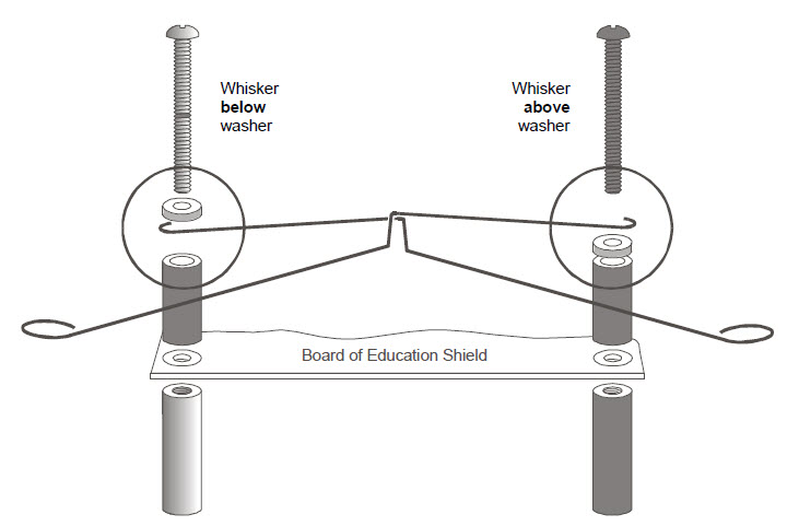
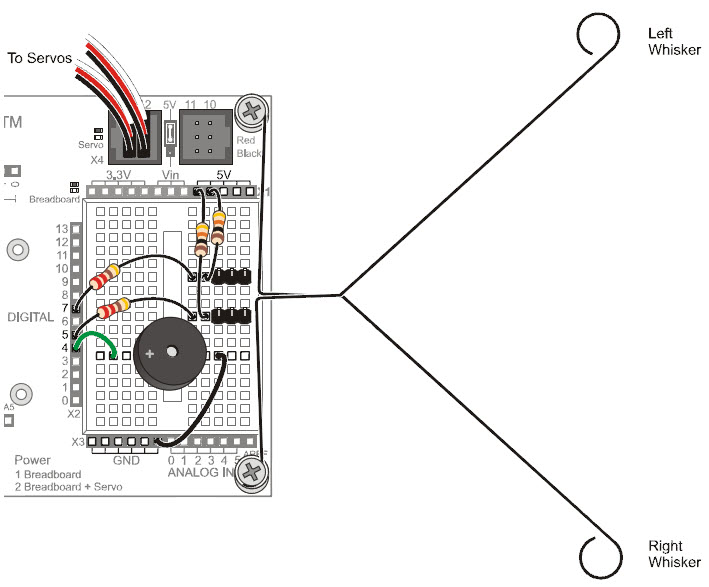
The whiskers are connected to ground (Vss) because the plated holes at the outer edge of the board are all connected to Vss. The metal standoffs and screws provide the electrical connection to each whisker.
Since each whisker is connected to digital I/O, the Arduino can be programmed to detect which voltage is applied to each circuit, 5 V or 0 V. First, set each pin to input mode with pinMode(pin, mode), and then detect the pin’s state, HIGH or LOW, with digitalRead(pin) function.
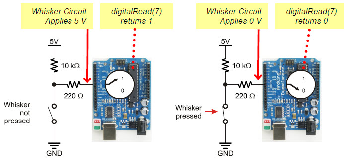
Take a look at the illustrations below. On the left, the circuit applies 5 V when the whisker is not pressed, so digitalRead(7) returns 1 (HIGH). On the right, the circuit applies 0 V when the whisker is pressed, so digitalRead(7) returns 0 (LOW).
Most importantly, your sketch can store the return values in variables, such as wLeft and wRight, and then use them to trigger actions or make decisions. The next example sketch will demonstrate how.
Switch Lingo: Each whisker is both the mechanical extension and the ground electrical connection of a normally open (off until pressed) momentary (on only while pressed) single-pole (one set of electrical contact points), single-throw (only one position conducts) switch.
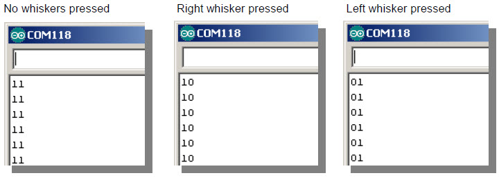
The next sketch tests the whiskers to make sure they are functioning properly, by displaying the binary values returned by digitalRead(7) and digitalRead(5). This way, you can press each whisker against its 3-pin header on the breadboard, and see if the Arduino’s digital pin is sensing the electrical contact.
When neither whisker is pressed up against its 3-pin header, you can expect your Serial Monitor to display two columns of 1’s, one for each whisker. If you press just the right whisker, the right column should report 0, and the display should read 10. If you press just the left whisker, the left column should report 1 and the display should read 01. Of course, if you press both whiskers, it should display 00.
Active-low Output
The whisker circuits are wired for active-low output, which means that they each send a low signal when they are pressed (active) and a high signal when they are not pressed. Since digitalRead returns 0 for a low signal and 1 for a high signal, 0 is what tells your sketch that a whisker is pressed, and 1 tells it that a whisker is not pressed.
/*
 * Robotics with the BOE Shield - DisplayWhiskerStates
 * Display left and right whisker states in Serial Monitor.
 * 1 indicates no contact; 0 indicates contact.
 */

void setup()                                 // Built-in initialization block
{
  tone(4, 3000, 1000);                       // Play tone for 1 second
  delay(1000);                               // Delay to finish tone
  pinMode(7, INPUT);                         // Set right whisker pin to input
  pinMode(5, INPUT);                         // Set left whisker pin to input

  Serial.begin(9600);                        // Set data rate to 9600 bps
}

void loop()                                  // Main loop auto-repeats
{
  byte wLeft = digitalRead(5);               // Copy left result to wLeft
  byte wRight = digitalRead(7);              // Copy right result to wRight

  Serial.print(wLeft);                       // Display left whisker state
  Serial.println(wRight);                    // Display right whisker state

  delay(50);                                 // Pause for 50 ms
}
These steps are important!
Seriously, you’ve got to make sure your circuit and code pass these tests before continuing. The rest of the examples in this chapter rely on the whiskers working correctly. If you haven’t tested and corrected any errors, the rest of the examples won’t work right.
In the setup function, pinMode(7, INPUT) and pinMode(5, INPUT) set digital pins 7 and 5 to input so they can monitor the voltages applied by the whisker circuits.
  pinMode(7, INPUT);          // Set right whisker pin to input
  pinMode(5, INPUT);          // Set left whisker pin to input
In the loop function, each call to digitalRead returns a 0 if the whisker is pressed or 1 if it is not. Those values get copied to variables named wLeft and wRight, which are short for whisker-left and whisker-right.
  byte wLeft = digitalRead(5);     // Copy left result to wLeft
  byte wRight = digitalRead(7);    // Copy right result to wRight
Next, Serial.print displays the value of wLeft to the Serial Monitor, and Serial.println displays the value of wRight and a carriage return.
  Serial.print(wLeft);             // Display left whisker state
  Serial.println(wRight);          // Display right whisker state
Before the next repetition of the loop function, there’s a delay(50). This slows down the number of messages the Serial Monitor receives each second. Although it’s probably not needed, we leave it in to prevent possible computer buffer overruns (too much data to store) for older hardware and certain operating systems.
Your sketch doesn’t actually need to use variables to store the values from digitalRead. Instead, the (1 or 0) value that digitalRead returns can be used directly by nesting the function call inside Serial.print and sending its return value straight to the Serial Monitor. In that case, your loop function would look like this:
void loop()                        // Main loop auto-repeats
{
  Serial.print(digitalRead(5));    // Display wLeft
  Serial.println(digitalRead(7));  // Display wRight

  delay(50);                       // Pause for 50 ms
}
