For a BOE Shield-Bot to follow a leader-object, it has to know the rough distance to the leader. If the leader is too far away, the sketch has to be able to detect that and move the BOE Shield-Bot forward. Likewise, if the leader is too close, the sketch has to detect that and move the BOE Shield-Bot backward. The purpose of the sketch is to make the BOE Shield-Bot maintain a certain distance between itself and the leader-object.
When a machine is designed to automatically maintain a measured value, it generally involves a control system. The value that the system is trying to maintain is called the set point. Electronic control systems often use a processor to take sensor measurements and respond by triggering mechanical actuators to return the machine to the set point.
Our machine is the BOE Shield-Bot. The measured value we want it to maintain is the distance to the leader-object, with a set point of 2 (for zone 2). The machine’s processor is the Arduino. The IR LED/receiver pairs are the sensors that take distance value measurements to the leader-object. If the measured distance is different from the set-point distance, the servos are the mechanical actuators that rotate to move the BOE Shield-Bot forward or backward as needed.
Closed loop control—repeatedly measuring a value and adjusting output in proportion to error for maintaining a set point—works very well for the BOE Shield-Bot shadow vehicle. In fact, the majority of the control loop shown in the diagram below reduces to just one line of code in a sketch. This block diagram describes the proportional control process that the BOE Shield-Bot will use to control the wheel speed based on detection distance measured with the IR LED/receiver pairs.
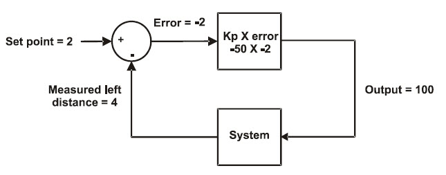
This block diagram could apply to either the left IR distance sensor and servo output or the right. In fact, your code will maintain two identical control loops, one for each side of the BOE Shield-Bot. Let’s walk through this example.
In the upper left, the set point = 2; we want the BOE Shield-Bot to maintain a zone-2 distance between itself and its leader-object. Below that, the measured distance is zone 4, so the leader-object is too far away. The arrows towards the symbols in the circle (called a summing junction) indicate that you add (+) the set point and subtract (-) the measured distance together to get the error, in this case 2 – 4 = -2.
Next, the error value feeds into the top square—an operator block. This block shows that the error gets multiplied by -50, a proportionality constant (Kp). In this example, the operator block gives us -2 × -50 = 100, so 100 is the output. In a sketch, this output value gets passed to the maneuver function. It turns the servo full speed forward to move the BOE Shield bot closer to the leader-object.
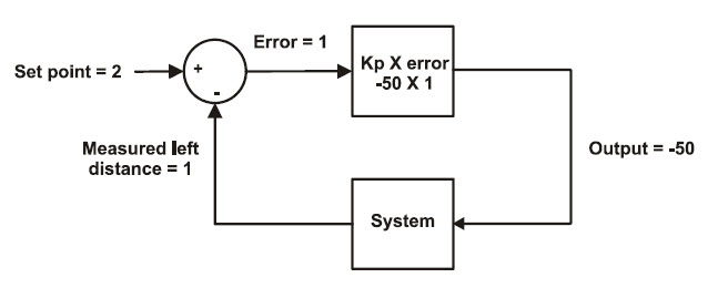
The next block diagram shows another example. This time, the measured distance is 1, meaning the leader-object is too close. So, the error is 1, and 1×–50 = -50. Passing -50 to the maneuver function turns the servo half-speed in reverse, backing the BOE Shield-Bot away from the leader-object.
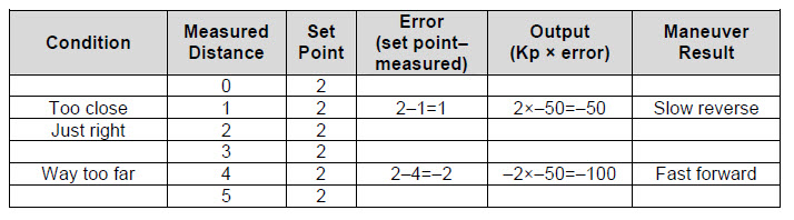
The next time through the loop, the measured distance might change, but that’s okay. Regardless of the measured distance, this control loop will calculate a value that will cause the servo to move to correct any error. The correction is always proportional to the error. The two calculations involved:
set point – measured distance = error; error x Kp = output for maneuver
…can be easily combined and re-ordered into one expression for your sketch:
Output for maneuver = (Distance set point – Measured distance) x Kp
If you want to take a look at the sketch in detail, see How FollowingShieldBot Works.
The FollowingShieldBot sketch repeats the proportional control loops just discussed at a rate of about 25 times per second. So, all the proportional control calculations and servo speed updates happen 25 times each second. The result is a BOE Shield-Bot that will follow your hand, a book, or another robot.
/*
 * Robotics with the BOE Shield - FollowingShieldBot
 * Use proportional control to maintain a fixed distance between
 * BOE Shield-Bot and object in front of it.
 */

#include <Servo.h>                           // Include servo library

Servo servoLeft;                             // Declare left and right servos
Servo servoRight;

const int setpoint = 2;                      // Target distances
const int kpl = -50;                         // Proportional control constants
const int kpr = -50;

void setup()                                 // Built-in initialization block
{
  pinMode(10, INPUT);  pinMode(9, OUTPUT);   // Left IR LED & Receiver
  pinMode(3, INPUT);  pinMode(2, OUTPUT);    // Right IR LED & Receiver

  tone(4, 3000, 1000);                       // Play tone for 1 second
  delay(1000);                               // Delay to finish tone

  servoLeft.attach(13);                      // Attach left signal to pin 13
  servoRight.attach(12);                     // Attach right signal to pin 12
}

void loop()                                  // Main loop auto-repeats
{
  int irLeft = irDistance(9, 10);            // Measure left distance
  int irRight = irDistance(2, 3);            // Measure right distance

  // Left and right proportional control calculations
  int driveLeft = (setpoint - irLeft) * kpl;
  int driveRight = (setpoint - irRight) * kpr;

  maneuver(driveLeft, driveRight, 20);       // Drive levels set speeds
}

// IR distance measurement function

int irDistance(int irLedPin, int irReceivePin)
{
  int distance = 0;
  for(long f = 38000; f <= 42000; f += 1000) {
    distance += irDetect(irLedPin, irReceivePin, f);
  }
  return distance;
}

// IR Detection function

int irDetect(int irLedPin, int irReceiverPin, long frequency)
{
  tone(irLedPin, frequency, 8);              // IRLED 38 kHz for at least 1 ms
  delay(1);                                  // Wait 1 ms
  int ir = digitalRead(irReceiverPin);       // IR receiver -> ir variable
  delay(1);                                  // Down time before recheck
  return ir;                                 // Return 1 no detect, 0 detect
}

void maneuver(int speedLeft, int speedRight, int msTime)
{
  // speedLeft, speedRight ranges: Backward  Linear  Stop  Linear   Forward
  //                               -200      -100......0......100       200
  servoLeft.writeMicroseconds(1500 + speedLeft);   // Set left servo speed
  servoRight.writeMicroseconds(1500 - speedRight); // Set right servo speed
  if(msTime==-1)                                   // if msTime = -1
  {
    servoLeft.detach();                            // Stop servo signals
    servoRight.detach();
  }
  delay(msTime);                                   // Delay for msTime
}
FollowingShieldBot declares three global constants: setpoint, kpl, and kpr. Everywhere you see setpoint, it’s actually the number 2 (a constant). Likewise, everywhere you see kpl, it’s actually the number -50. Likewise with kpr.
const int setpoint = 2;                      // Target distances
const int kpl = -50;                         // Proportional control constants
const int kpr = -50;
The convenient thing about declaring constants for these values is that you can change them in one place, at the beginning of the sketch. The changes you make at the beginning of the sketch will be reflected everywhere these constants are used. For example, by changing the declaration for kpl from -50 to -45, every instance of kpl in the entire sketch changes from ‑50 to -45. This is exceedingly useful for experimenting with and tuning the right and left proportional control loops.
The first thing the loop function does is call the irDistance function for current distance measurements and copies the results to the irLeft and irRight variables.
void loop()                                  // Main loop auto-repeats
{
  int irLeft = irDistance(9, 10);            // Measure left distance
  int irRight = irDistance(2, 3);            // Measure right distance
Remember the simple control loop calculation?
Output for maneuver = (Distance set point – Measured distance) x Kp
The next two lines of code perform those calculations for the right and left control loops, and store the output-for-maneuver results to variables named driveLeft and driveRight.
  // Left and right proportional control calculations
  int driveLeft = (setpoint - irLeft) * kpl;
  int driveRight = (setpoint - irRight) * kpr;
Now, driveLeft and driveRight are ready to be passed to the maneuver function to set the servo speeds.
  maneuver(driveLeft, driveRight, 20);       // Drive levels set speeds
}
Since each call to maneuver lasts for 20 ms, it delays the loop function from repeating for 20 ms. The IR distance detection takes another 20 ms, so the loop repetition time is about 40 ms. In terms of sampling rate, that translates to 25 samples per second.
Sampling Rate vs. Sample Interval
The sample interval is the time between one sample and the next. The sampling rate is the frequency at which the samples are taken. If you know one term, you can always figure out the other:
sampling rate = 1 ÷ sample interval
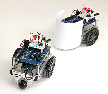
Here's a leader BOE Shield-Bot followed by a shadow BOE Shield-Bot. The lead robot is running a modified version of FastIrRoaming (with maneuver speeds reduced to +/- 40). The shadow BOE Shield-Bot is running FollowingShieldBot. One lead robot can string along a chain of 6 or 7 shadow robots. Just add the paper panel to the rest of the shadow BOE Shield-Bots in the chain.

/*
 * Robotics with the BOE Shield - SlowerIrRoamingForLeaderBot
 * Adaptation of RoamingWithWhiskers with IR object detection instead of
 * contact switches
 */

#include <Servo.h>                           // Include servo library

Servo servoLeft;                             // Declare left and right servos
Servo servoRight;

void setup()                                 // Built-in initialization block
{
  pinMode(10, INPUT);
  pinMode(9, OUTPUT);   // Left IR LED & Receiver
  pinMode(3, INPUT);
  pinMode(2, OUTPUT);    // Right IR LED & Receiver

  tone(4, 3000, 1000);                       // Play tone for 1 second
  delay(1000);                               // Delay to finish tone

  servoLeft.attach(13);                      // Attach left signal to pin 13
  servoRight.attach(12);                     // Attach right signal to pin 12
}

void loop()                                  // Main loop auto-repeats
{

  int irLeft = irDetect(9, 10, 38000);       // Check for object on left
  int irRight = irDetect(2, 3, 38000);       // Check for object on right

  if((irLeft == 0) && (irRight == 0))        // If both sides detect
  {
    maneuver(-40, -40, 20);                // Backward 20 milliseconds
  }
  else if(irLeft == 0)                       // If only left side detects
  {
    maneuver(40, -40, 20);                 // Right for 20 ms
  }
  else if(irRight == 0)                      // If only right side detects
  {
    maneuver(-40, 40, 20);                 // Left for 20 ms
  }
  else                                       // Otherwise, no IR detects
  {
    maneuver(40, 40, 20);                  // Forward 20 ms
  }
}

int irDetect(int irLedPin, int irReceiverPin, long frequency)
{
  tone(irLedPin, frequency, 8);              // IRLED 38 kHz for at least 1 ms
  delay(1);                                  // Wait 1 ms
  int ir = digitalRead(irReceiverPin);       // IR receiver -> ir variable
  delay(1);                                  // Down time before recheck
  return ir;                                 // Return 1 no detect, 0 detect
}

void maneuver(int speedLeft, int speedRight, int msTime)
{
  // speedLeft, speedRight ranges: Backward  Linear  Stop  Linear   Forward
  //                               -200      -100......0......100       200
  servoLeft.writeMicroseconds(1500 + speedLeft);   // Set left servo speed
  servoRight.writeMicroseconds(1500 - speedRight); // Set right servo speed
  if(msTime==-1)                                   // if msTime = -1
  {
    servoLeft.detach();                            // Stop servo signals
    servoRight.detach();
  }
  delay(msTime);                                   // Delay for msTime
}
You can adjust the setpoint and proportionality constants to change the shadow BOE Shield-Bot’s behavior. Use your hand or a piece of paper to lead the shadow BOE Shield-Bot while doing these exercises:
You might notice some odd behaviors. For example, if the set point is 0, it won’t back up. Want to figure out why?
