The Parallax 2-Axis Joystick can be used for a wide variety of projects like wheeled robots, video games, or anything requiring user input. Like most joysticks, the Parallax 2-Axis Joystick uses two variable resistors (called potentiometers) to read the user’s input. Remember reading a potentiometer’s value back in Measure Volts? Reading a joystick’s position is a matter of measuring two potentiometer voltages. One reports the left/right position and the other reports the up/down position.
Circuit
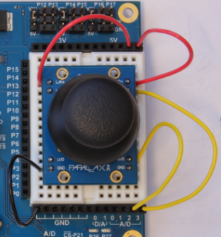
The Parallax joystick contains two 10 kΩ potentiometers, one for each axis. We’ll read the value from the potentiometer using an analog to digital converter, or ADC, just like in Measure Volts. For our joystick, we’ll use one of the ADC’s inputs for each axis. In this case, up/down (U/D) is connected to channel 2 and left/right (L/R) is connected to channel 3. The potentiometer also needs to be powered, so we’ll attach the potentiometer’s pins labeled L/R+ and U/D+ to 5 V, and the GND pin to ground. Note that there are two of some of these pins—it doesn’t matter which one you use, they are electrically the same.
Parts
(1) Parallax 2-Axis Joystick (#27800)
- Build the circuit as shown below.

Note: This lesson is designed for the Propeller Activity Board (original or WX version). It is not compatible with the Propeller Board of Education, which uses a different A/D converter.
Test Code
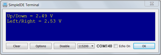
This test code will read both axes of the joystick and display voltage values for each. Since the potentiometer is connected to 5 V, the middle of the joystick (where it goes when you release it) will display 2.5 V on both axes. You may notice slight deviations from 2.5 V; this is explained more in the Did You Know? section.
- If you haven't already installed the latest USB driver, SimpleIDE, or Learn folder, go to Propeller C - Set up SimpleIDE and Propeller C - Start Simple
- Open joystick_adc.side from ... Documents\SimpleIDE\Learn\Examples\Devices\Sensor\Joystick.
- Click the Run with Terminal button.
- Verify that you get voltage readings like those shown below.
- Try moving the joystick around. Do the voltages vary from 0 to 5 V, as you’d expect? What happens at the corners?
How it Works
The code includes the adcDCpropAB library with the command #include "adcDCpropAB.h". This library is designed for measuring voltages using the A/D converter on the Propeller Activity Board (original or WX version). The function adc_init gets called first, to tell it which Propeller I/O pins are connected to the A/D converter's /CS, SCL, DO and DI pins. Together these pins are called an SPI bus, over which the Propeller communicates with many peripheral devices. You will find the SPI pin numbers next to the A/D converter chip, which is right below the GND sockets on your board.
After that function, float x, y declares two floating point variables for storing measurements. Inside the while(1) loop, udV = adc_volts(2) stores the voltage at A/D2 into the udV variable, and lrV = adc_volts(3) does the same for A/D3. A couple of print calls display the two voltage values, followed by a 1/10 second pause before the loop repeats.
/*
  Joystick.c

  Simple demo with the Parallax 2-axis Joystick.
*/
#include "adcDCpropab.h"                            // Include adcDCpropAB
#include "simpletools.h"                            // Include simpletools


int main()                                          // Main function
{
  adc_init(21, 20, 19, 18);                         // CS=21, SCL=20, DO=19, DI=18

  float lrV, udV;                                   // Voltage variables

  while(1)                                          // Loop repeats indefinitely
  {
    udV = adc_volts(2);                             // Check A/D 2
    lrV = adc_volts(3);                             // Check A/D 3

    putChar(HOME);                                  // Cursor -> top-left "home"
    print("Up/Down = %.2f V %c\n", udV, CLREOL);    // Display voltage
    print("Left/Right = %.2f V %c\n", lrV, CLREOL); // Display voltage

    pause(100);                                     // Wait 1/10 s
  }
}
Did You Know?
- A/D Converter Range: The Propeller Activity Board’s A/D converter sends numbers ranging from 0 to 4095, which represent values that range from 0 to 4.99878 V. If you supply it with 5 V, it’ll still display 4095, which is the highest it can go. These raw A/D values represent the number of 4096ths of 5 V.
- Output and Tolerance: You may have noticed that when you let up on the joystick the voltages are not exactly 2.5 V. For example, our joystick rests around 2.49 V in the Up/Down axis (y axis) and 2.53 V in the Left/Right axis (x axis). This is due to the way potentiometers are manufactured. Like all electronic devices, potentiometers have tolerances, meaning the permissible range of variation in the output (for example, ±10%). For any two devices, the tolerances often do not fall in the same direction, as is the case with the potentiometers in this particular joystick. Many video game controllers allow a “dead zone” in the middle of the joystick to correct for this effect.
Try This
Instead of displaying the voltage values from the joystick, let’s display a range representing the joystick's position. To do this, we’ll need to scale voltages going from 0 to 5 V into values from -100 to 100.
- Use the Save Project As button to save a copy of your project in …Documents\SimpleIDE\My Projects.
- Modify the main function as shown below.
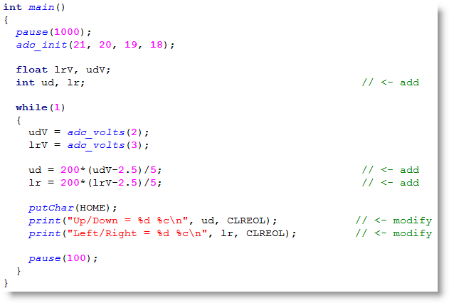
- Run the program and verify that you see values between -100 and 100 instead of voltages for each axis.
Your Turn
You may want to drive a servo with your joystick. Perhaps you want your servo to start at 90 degrees and move ±60 degrees from there. Write some code to do this scaling, and output the result for each axis on the terminal.
- This is a simple application of y=mx + b. In the example above, m was 40 and b was -2.5/40. See if you can figure out the new equation for the servo application.
- Try changing the program in Try This to display 0 to 100% instead of -100 to 100.
Hint: to display the “%” character in the serial terminal, we need to type two of them in the print command. This is because % acts as a special operator in print commands so it is necessary to have two % characters tell print to display a literal “%.”