On this page, we'll go through MMA7455 Test Z Axis.c a little bit at a time to see how the shift_out and shift_in functions communicate with the SPI device.
This is the part where you’ll want to go get the MMA7455 datasheet. Each time you run into a term like MCTL or ZOUT8, use your .pdf reader’s search function to find and read about all instances of each term. As you do so, it will help build a picture of how to use a device’s datasheet to write code to communicate with the device.
Get the Datasheet
- Go to www.parallax.com and search for 28586.
- Go to the sensor’s product page, and click the Downloads dropdown.
- Download the Freescale Semiconductor manufacturer’s datasheet. It’s the link titled: MMA7455 3-Axis Accelerometer Device Documentation.
- Open it and have it ready to search in your PDF reader.
Include Library and Global Variable
The program includes the simpletools library since it uses pause, print and a number of other simpletools functions. The simpletools library also has functions named shift_in for receiving SPI data and shift_out for transmitting it.
#include "simpletools.h" // Include simpletools lib
An int variable named z is declared for storing the z-axis accelerometer measurement.
signed char z; // Z-axis value
Initialize the I/O Bus Pins
The first two statements in the main function initialize the I/O pins connected to the SPI bus, getting them ready for the communication signaling to come. The high(6) call sets the chip’s chip select (CS) line high, which tells the chip that it doesn’t have to communicate at the moment. The low(8) call sets the I/O pin connected to the chip’s CLK line low, preparing it to send brief high signals called clock pulses.
int main()                            // Main function
{
  high(6);                            // CS line high (inactive)
  low(8);                             // CLK line low
Configure the SPI device
The accelerometer’s datasheet has instructions for configuring the chip’s mode of operation, which must be done before reading measurements from it. Configuring the mode entails sending several values to the chip using SPI signaling. But, before sending any values, the microcontroller has to set the chip’s /CS line low, which tells the accelerometer chip to wake up and pay attention to signals that it’s about to receive on the CLK and DATA lines. Since Propeller I/O pin P6 is connected to the chip’s /CS pin, low(6) does the job.
Next, the microcontroller has to send a set of three values on the data line. Each value has to have a certain number of bits, that is, binary 1/0 digits. The first value has 7 bits, followed by a 1-bit value, and then an 8-bit value. A brief high pulse to the CLK line tells the chip to get each bit one at a time from the DATA line. If the DATA line is high, the chip interprets that bit as a binary 1. If it’s low, the chip interprets that as a binary 0.
You can see these signals on the CS, CLK, and DATA lines below.

The simpletools library has a function called shift_out that takes care of setting DATA line values and sending pulses to the CLK line. In the drawing above, you can see how a separate shift_out call was used for the 7-bit, 1-bit, and 8-bit values needed for configuring the sensor.
The shift_out function has five parameters: pinDat, pinClk, mode, bits, and value. Let’s look at what’s happening with each parameter in the first call: shift_out(7, 8, MSBFIRST, 7, 0b1010000).
Let’s look at each parameter:
- pinDat = 7 because P7 is the Propeller I/O pin connected to the chip’s DATA pin
- pinClk = 8 because P8 is the Propeller I/O pin connected to the chip’s CLK pin
- mode = MSBFIRST, meaning “most significant bit first.” It tells shift_out to send the value’s leftmost binary digit (called the most significant bit) first and work to the right. The other option is LSBFIRST (least significant bit first), which would tell shift_out to send the rightmost binary digit first, and work left.
- bits = 7, meaning that 7 binary digits get transmitted.
- value = 0b1010110. It’s the 7-bit value to be transmitted, using the binary prefix 0b followed by the actual seven binary digits.
After that, two more shift_out commands send two more binary values. The first is a single-bit value 0b0, and the second is the 8-bit value 0b01100101.
So, how did we know to send those values? The answer is, someone had to read the MMA7455 datasheet, understand how the device needed to be configured, and then write code to send those configuration messages. Each device will be different, so it’s a necessary step in writing SPI drivers. A chip’s datasheet will include descriptions of its registers (small bits of memory) that your program will need to read or write to in order to use the device. A register typically has a name to identify its purpose, and an address to use when interacting with it.
The MMA7455 datasheet explains that the first step in configuration is to send a 7-bit command. This command has to tell the chip whether your program will send a value to be stored in one of the chip’s registers (write operation) or if the chip is going to have to tell you what value a certain register stores (read operation). The leftmost digit in the binary command value has to be set to 1 for write or 0 for read. The next six binary digits have to contain the address of the chip’s memory where this value is going to get stored.
The configuration register is named MCTL, and its address is 0x16 (hexadecimal 16). Converting to decimal, that’s 1x16 + 6x1 = 22. In 6-bit binary, that’s 010110 = 0x32 + 1x16 + 0x8 + 1x4 + 1x2 + 0x1. The 7th binary digit (counting from the right) has to be a 1 for a write operation. That gives us 1010110. With the 0b prefix added, our command for the value parameter is 0b1010110. (Don't worry, we’ll take a look at an easy way to let your code handle the hexadecimal-to-binary conversion later).
shift_out(7, 8, MSBFIRST, 7, 0b1010110); // Write MCTL register
Next, the datasheet says that the chip needs to receive a “don’t care” value. Basically, that means it needs to receive a pulse on the CLK line, with either a 1 or 0 (we don’t care) on the DATA line. This shift_out call does the job, sending 0b0 for the value parameter, though we could have used 0b1.
shift_out(7, 8, MSBFIRST, 1, 0b0); // Send don't-care value
Now that the program is done telling the chip to get ready to receive a value that it has to write to its MCTL register (at address 0x16), it’s time to actually send that value. The value that makes it measure acceleration in the +/- 2g range is 0b01100101.
shift_out(7, 8, MSBFIRST, 8, 0b01100101); // Value for MCTL register
The datasheet explains each binary value in the 8-bit MCTL register, and the effect those values have on the chip’s operation. Here is what the summary table for that register looks like in the datasheet:
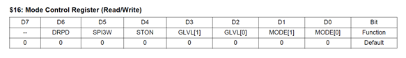
The top row is the binary digit number or bit number, from 7 on the left to 0 on the right. The second row is the name given to each the bit. It uses these names to discuss each binary digit and what setting it to 1 or 0 does to the chip’s configuration. Our 0b01100101 command sets the unnamed D7 bit to 0; it is another “don’t-care” bit. It also sets DPRD to 1, SPI3W to 1, STON to 0, GLVL[1] and GLVL[0] to 01, and mode[0] and mode[1] to 01. The datasheet goes on to explain what setting each bit to 1 or 0 does. We will have to leave you to research those, since it is part of getting an SPI device to work.
The high(6) call ends the SPI exchange by setting the P6 I/O pin that controls the chip’s /CS input high.
high(6); // CS -> high stop SPI
Request and Read the Sensor Output
Now that the chip is configured, the program enters a loop that repeatedly gets z-axis measurements from the chip and displays them.
  while(1)                            // Main loop
  {
Getting the z-axis value requires another command, again using a set of 7-bit, 1-bit, and 8-bit values. The datasheet says the chip’s ZOUT8 register stores the signed 8-bit version of the z-axis measurement, so we want to read the values in that register.
As before, the first step is to bring the chip’s /CS pin low, with low(6). The ZOUT8 register’s address in the chip is 0x08 (hexadecimal 8), which expressed as a 6-bit binary number is 001000. Remember that the chip’s datasheet said for a read operation, we want to set bit 6 (the 7th binary digit from the right) to 0. That, with the prefix, makes our 7-bit command 0b0001000 for the value parameter in the call shift_out(7, 8, MSBFIRST, 7, 0b0001000). This command must also be followed by a “don’t care” bit, done with shift_out(7, 8, MSBFIRST, 1, 0b0).

Now that the sensor chip received the read ZOUT8 register command, it has to reply with the value stored in its ZOUT8 register. To receive this reply, the Propeller chip still has to apply pulses to the CLK line. But now it has to listen for values the accelerometer chip sends on the DATA line. The counterpart of shift_out is shift_in. This function still outputs pulses to the CLK line, but it sets its I/O pin on the DATA line to input and monitors for reply values from the chip. So, z = shift_in(7, 8, MSBPRE, 8), reads data on P7, sends clock pulses on P8, in MSBPRE mode, and it reads 8 bits.
MSBPRE is one of four options the shift_in function’s mode parameter can use. The MSB part is similar to MSBFIRST — it takes the first binary digit, and loads it into the function result value’s leftmost binary digit, and works its way to the right. Change it to LSB, and it would load the first binary digit into the result variable’s rightmost binary digit and work its way left. The PRE part tells shift_in to check for a value on the DATA line before each clock pulse. If that were changed to POST, it would check after each pulse. The result in the figure is 01000000, which converted from binary is 0x128 + 1x64 + 0x32 + 0x16 + 0x8 + 0x4 + 0x2 + 0x1 = 64 (same as the SimpleIDE display). The high(6) call sets /CS high again, disabling the chip and ending the SPI transaction.
Printing the Sensor Data
Before repeating the while(1) loop, the program displays the value returned by the shift_in function call, which was stored in the z variable.
    print("%c z = %d%c", HOME, z, CLREOL);        // Display measurement
    pause(500);                                   // Wait 0.5 s before repeat
  }
}
Congrats for making it this far! The next page shows you some techniques to make the coding easier.