Let's build the BlocklyProp code for programming your Tilt Tones musical instrument, and take a look at how it works.
Tilt Tones BlocklyProp Code
- Create a new project named Tilt Tones.
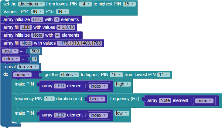
- Build the project shown below, and save it.
- Click the Load and run button (save code to EEPROM on your board).
- Tilt your board forward and backward, left and right. In each position, it should play a different tone and light a different LED for 500 milliseconds.
How the Tilt Tones Project Works
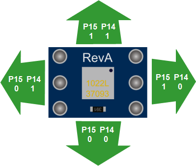
The 4-Directional Tilt Sensor uses two I/O pins; we connected to P14 and P15 in our project. The diagram below shows what each I/O pin will detect when the sensor is tilted in each direction, either a one or a zero. There are four output states for the sensor: binary 11 = 3, binary 10 = 2, binary 01= 1, and binary 00 = 0.
The code begins with a set multiple pins block. It is configured to set the directions for I/O pins P14 and P15 to IN (input), so the Propeller can receive signals from the Tilt Sensor.
The next task is to initialize and fill two arrays, each with four elements. Why four elements? One for every output state that the Tilt Sensor can provide. The LED array holds the I/O pin numbers for the LED circuits built on the breadboard. The Note array holds four different frequencies, which will be used to play notes on the piezo speaker.
Then, two set variable blocks declare and initialize variables. First, you will set the beat variable to 500, and it will be used later when playing tones. The index variable gets an initial value of zero, and it will be used to access array elements.
The action happens inside a repeat forever loop. The binary get pins block reads the input states of a contiguous group of I/O pins, and the state of each I/O pin becomes a bit in a binary number. The highest I/O pin number provides the most significant bit. Our block uses P15 and P14, so the possible values are binary 11 = 3, binary 10 = 2, binary 01= 1, and binary 00 = 0. In this way, the output state of the Tilt Sensor is stored as a binary number in the index variable.
Now, the freshly-set index variable will be used to select the element at the value of that position from the LED and Notes arrays in the next three blocks. For example, if you tilt the board towards you, P14 and P15 both detect 0, making the value of index 00, which means it grabs element 0 from the array.
To turn on an LED, the index variable is put inside a get array [LED] element block, which is inside a programmable make PIN block. Using the above example, the 0th element in the LED array is 4, so the LED on P4 lights up when this block sets it high.
To play a note, the index variable is used inside the get array [LED] element block, which is inside a frequency out block. To continue with the example, the 0th element of the note array is 1175. That frequency plays for 500 ms - the value of the beat variable used in the duration (ms) field.
After the note plays, the loop finishes with a second make PIN block. Like the first one, it uses the indexed array [LED] element, setting the I/O pin low to turn off the LED off before the loop repeats.