The True Colors project was built with six servos mounted inside a 1-1/2 inch deep cradled wood panel, with a small painted canvas panel attached to each servo's horn. A LaserPING))) Rangefinder's output is used to set the servos' positions.
Materials List
- (1) Propeller Activity Board WX (#32912)
- (6) Parallax Standard Servos (#900-00005)
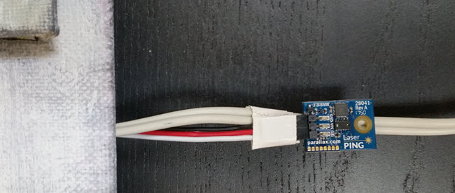
- (1) LaserPING 2m Rangefinder (#28041)
- (1) 3-wire Extension Cable (#800-00120)
- (1) 3-pin single row header with long pins (#451-00303)
- Wall-mount power supply, 2.1mm center-positive (such as #750-00009)
- Assorted jumper wires
- Cradled wood panel, at least 1-1/2" deep (I used Blick Studio #07045-1010)
- Assorted canvas panels (I used 4 5x5, 1 6x6, and 1 4x6 inch panels)
- Double-sided sticky foam tape
- Paints or other art medium (I used Utrecht Studio acrylics)
To plan the canvas panel placement, I tried various compositions by just resting the canvases in place and took a quick picture when I was satisfied. The mounting holes were laser cut here at Parallax to fit the servo case and mounting screws (shout out to Kenneth in the machine shop!) A large hole was drilled in the bottom of the frame to run the power cord, and two smaller holes in the top frame to help with hanging.

When mounting the servos, I first removed the servo horns. Then I used stacks of Nylon nuts as spacers, so the servo horns rest at different heights above the wooden front surface. This allows the canvas panels attached to the servo horns to overlap and rotate with minimal collision.

Next, I removed the screw from each servo horn but left it on its spline, then topped it with a piece of foam sticky tape. Finally I pressed each canvas in place. This allows the squares to be removable for painting and for adjusting the servo's default rotation position. Here is the piece disassembled after the painting is complete.

The servos plug into the 3-pin servo ports on the Propeller Activity Board WX, which connects them to Propeller I/O pins P12–P17. BE SURE to put the servo port power jumpers to 5V if you are using wall-mount power supply greater than 6V! The LaserPING rangefinder connects to P0, 3.3 VDC, and Ground with the extension cable, 3-pin header, and jumper wires in the prototyping area.

I used a wall-mount power supply to provide adequate current for all 6 servos to move at once. The LaserPING board is taped to the power cord far down enough so that the rotating canvas squares do not intercept its laser beam and cause it to trigger itself.
CAUTION: If you are using a wall-mount power supply greater than 6 VDC, be sure to put the servo port power jumpers into the 5V position to avoid exposing the servos to more than 6 VDC.