Schematics and Building the Circuits
Figure 1 – Tilt Tones Schematics (Propeller Activity Board)
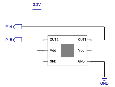
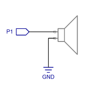
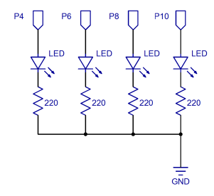
Figure 1 shows the schematics for connecting the 4-Directional Tilt Sensor, Piezo Speaker and 4 LED lights.
Figure 2 – Tilt Tones Wiring Diagram (Propeller Activity Board)
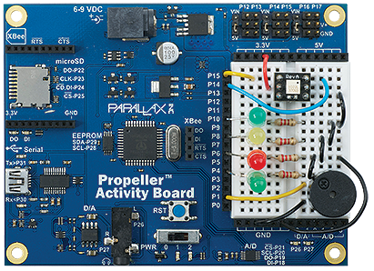
When you have finished setting up your board, it should look something like the wiring diagram in Figure 2. If your LED leads are too long, they can be cut, but be sure to make note of which side is the cathode, and which is the anode. If you look at the top of the LED, the cathode is the side where the edge is either flattened or has a small notch in it.