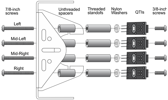
Each QTI sensor is connected to a post that is mounted on the underside of the chassis. This positions the sensors right above the ground surface.
- Assemble the QTI sensors and mount them to the underside of the cyber:bot chassis:
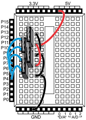
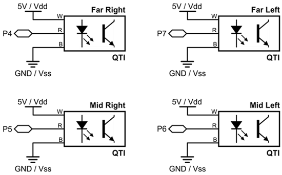
Each QTI sensor needs to connect to 5 V power, a cyber:bot I/O pin, and ground. For this, you will use the four 3-pin headers from the kit to build ports on the breadboard for each sensor.
- Build the header circuits as shown in the schematic and wiring diagram below. The 3-pin headers and jumper wires are in your QTI Line Follower kit.
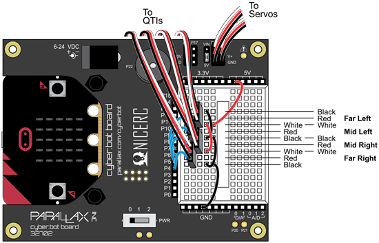
- Plug a 3-pin extension cable into each QTI sensor. Match the color of the wires to the B R W (black, red, white) labels on the sensor.
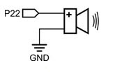
- If you don't already have it in place, install your piezospeaker into the dedicated P22 spot on your board. You'll need it for this project.
- Connect the extension cable from each QTI sensor and to its header circuit on the breadboard. Match the color of the wires to the diagram below. Take your time - getting this correct is important!