Gather the Parts
For this construction step, you will need:
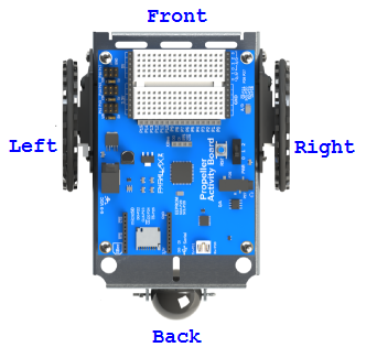
- Assembled ActivityBot 360°
- (5) AA batteries, alkaline or NiMH
- Needle-nose pliers - optional, but helpful
- Masking tape
- Pen
Battery Type Matters!
The Feedback 360° servos do best 6 to 8 volts. Five alkaline batteries provide 5 x 1.5 V = 7.5 V. Five NiMH batteries provide 5 x 1.2 V = 6 V. NiMH batteries perform well, but Ni-Cad rechargeable batteries do not perform well in this application and are not recommended.
Label the Cables
- If you have not done so already, put a masking tape label on the end of each servos' cables.
- Trace each cable back to its origin to see where it is connected.
- Label each cable Right or Left.
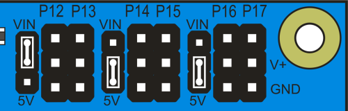
Prepare the Servo Ports
Each pair of 3-pin servo ports along the top of the Propeller Activity Board (original or WX version) has a shunt jumper on power-select pins to its immediate left.
IMPORTANT! Make sure there are no cables plugged into the board. Moving jumpers with power connected could damage your board.
- Unplug the USB cable and battery pack if you have either of them plugged into the board.
- Move the shunt jumpers into the configuration shown below. Tip: If your jumpers do not have a little tab on them, needle-nose pliers will help.
- P12 & P13: VIN
P14 & P15: 5V
P16 & P17, 5V
Missing a Voltage Selection Jumper? Replacements are available - contact our sales department to order part #452-00043; there are three per board.
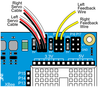
Plug In the Cables
Each servo has a 3-wire cables: white = signal, red = power, black = ground. When plugging these cables into servo headers, be sure to align white wires with the P12 & P13 labels along the edge of the PCB, and the black wires along the row labeled GND (see the picture below).
The Feedback 360° servo also has a single yellow feedback wire, which plugs into a separate servo header's I/O pin.
- Plug the servo's white-red-black cables into these servo ports
P12: Left Servo
P13: Right Servo - Plug the encoders into these servo ports, making sure the white or yellow signal line connects to the port's I/O pin, right by the P14 & P15 labels near the edge of the PCB.
P14: Left Feedback Wire
P15: Right Feedback Wire
Double-check your Connections
- P12 & P13 servo port shunt jumper — Set to VIN
- P14 & P15: servo port shunt jumper — Set to 5V
- Left servo cable — P12 servo port
- Right servo cable — P13 servo port
- Left feedback wire — P14 servo port I/O pin, closest to the edge of the board
- Right feedback wire — P15 servo port I/O pin, closest to the edge of the board
Insert the Batteries
- Place (5) AA batteries into the battery pack.
- Plug the battery pack's barrel plug into the board's barrel jack.