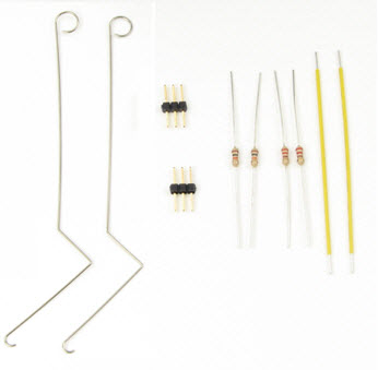
Parts List
- (2) Whisker wires
- (2) 3-pin headers
- (2) 10 kΩ resistors (brown-black-orange)
- (2) 220 Ω resistors (red-red-brown)
- (misc) Jumper wires
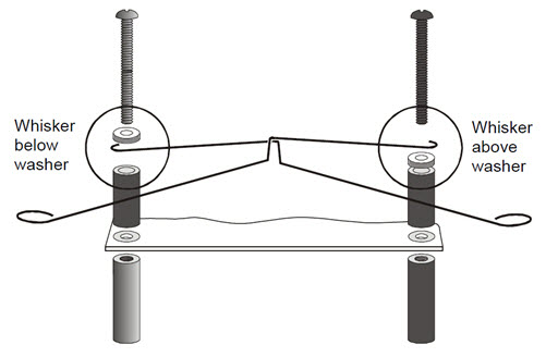
Adding the Whiskers
- Loosen the two screws that attach the front of your board to the chassis standoffs.
- Hook a whisker wire onto each screw, positioned as shown in the diagram below.
- Make sure to set one whisker above the nylon washer, and the other below, as shown here.
- Gently re-tighten the screws, making sure the edge of the wire is parallel to the edge of the breadboard.
Build the Circuit
The next picture shows whisker wiring. Along with the whisker circuits, it has the same piezospeaker we've been using.
- Build the circuit as in the picture.
- Make sure to leave some space between the whiskers and the 3-pin headers.
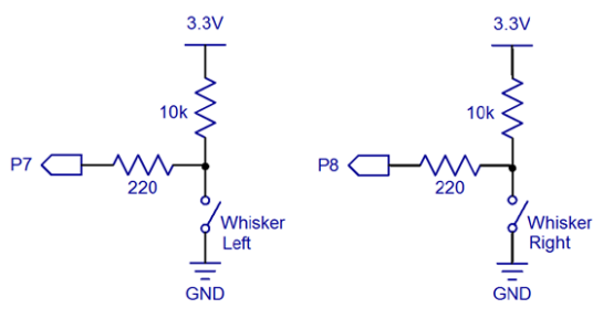
- Also make sure that the 10 kΩ resistors (brown-black-orange) are the ones that connect 3.3 V sockets to the rows with the 3-pin headers.
- Likewise, the 220 Ω (red-red-brown) resistors should connect P8 and P7 to the 3-pin header rows.
- Ignore the 20k resistors connecting P14 & P15 to the 3.3V header, if your kit is using the Feedback 360 servos with the yellow signal wire.
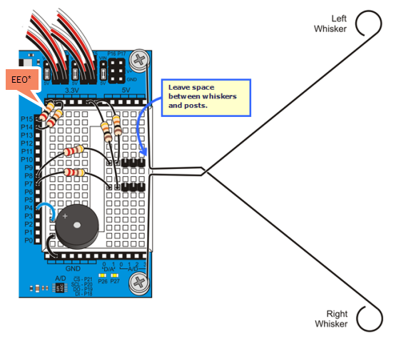
*P14/P15 resistors are only needed for ActivityBot kits using External Encoders (#32500).