Now, it's time to build and test two phototransistor circuits to give your ActivityBot phototransistor "eyes." Leave the piezo speaker circuit in place.
Parts
- (2) Phototransistor (#350-00029)
- (2) 0.01 µF capacitor (labeled 103)
- (2) 220 ohm resistor (red-red-brown)
Build the Light Sensor Circuits
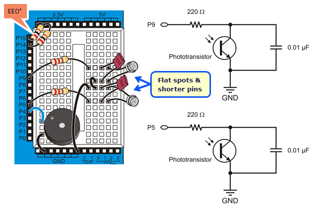
Build the circuit shown below.
- Make sure the phototransistor's shorter leads and flat spots are connected to ground, as shown in the wiring diagram below.
- Use the 0.01 µF capacitors, labeled "103." The capacitors in your ActivityBot kit are not polar; it does not matter which way you plug them in.
- Point the phototransistors upwards and outwards, about 90° from each other, and about 45° from vertical.
- Ignore the 20k resistors connecting P14 & P15 to the 3.3V header, if your kit is using the Feedback 360 servos with the yellow signal wire.
*P14/P15 resistors are only needed for ActivityBot kits using External Encoders (#32500).
Test the Light Sensor Circuits
This test will display raw light sensor readings in the SimpleIDE Terminal. You will need a flashlight or lamp that is brighter than the overall light level in the room.
The phototransistor circuits are designed to work well indoors, with fluorescent or incandescent lighting. Make sure to avoid direct sunlight and direct halogen lights; they would flood the phototransistors with too much infrared light.
- In your robotics area, close window blinds to block direct sunlight, and point any halogen lamps upward so that the light is reflected off the ceiling.
- Click SimpleIDE’s Open Project button.
- Open Test Light Sensors.side from ...Documents\SimpleIDE\Learn\Examples\Robots\ActivityBot.
- Put the power switch in Position 1.
- Click the Run with Terminal button.
- Hold your hand over one phototransistor, and then the other, while watching the values change.
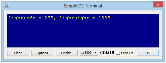
The values shown above were taken in a room with overhead fluorescent lighting. Notice how the lightRight measurement is larger - this was caused by cupping a hand over the right phototransistor.
Mismatched Measurements
It is unlikely that your two phototransistor measurements will match exactly. Each individual sensor will vary slightly as a natural part of the manufacturing process, and the brightness levels are rarely precisely even in any environment However, if one gives a measurement about 100 times larger than the other when exposed to the same level of light, that phototransistor is probably in backwards. Check your circuit and try again.
How it Works
This simple program starts by declaring two int variables, lightLeft and lightRight, to hold values returned by the left and right phototransistor circuits.
The action happens inside a while(1) loop, which takes two light sensor measurements and displays the results over and over again.
Recall from the Sense Light tutorial that phototransistor measurement is a two-step process. First, high(9) connects the phototransistor circuit to 3.3 V, allowing the capacitor in the circuit to charge up like a tiny battery. It only takes a moment to do that; pause(1) allows enough time. Immediately after charging the circuit, the next line of code calls the rc_time function to take a measurement at I/O pin 9 and store the result in lightLeft. The same steps are taken to store a sensor measurement in lightRight.
After that, the print statement prints the name of each variable followed by its value in decimal. The control character HOME returns the cursor to the upper left corner of the SimpleIDE terminal each time, and CLREOL clears out any characters left over from the previous measurement.
/*
  Test Light Sensors.c
*/

#include "simpletools.h"

int lightLeft, lightRight;

int main()
{
  while(1)
  {
    high(9);
    pause(1);
    lightLeft = rc_time(9, 1);

    high(5);
    pause(1);
    lightRight = rc_time(5, 1);

    print("%clightLeft = %d, lightRight = %d%c",
           HOME, lightLeft, lightRight, CLREOL);
    pause(250);
  }
}
Did you Know?
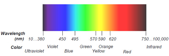
Light travels in waves so small that the distance between adjacent peaks is measured in nanometers (nm), which are billionths of meters. The figure below shows the wavelengths for colors of light we are familiar with, along with some the human eye cannot detect, such as ultraviolet and infrared. The phototransistor in your ActivityBot kit detects visible light, but is most sensitive to 850 nm wavelengths, which is in the infrared range.
Your Turn
Just for fun, let's see if the phototransistor can detect different colors.
- Zoom in on the color wavelenghth graph above.
- Re-run Test Light Sensors.side.
- Hold your robot up to the screen, placing one phototransistor very close to the color bar.
- What color gives the highest reading? What colors give the lowest?
From your observation, do you think a clear phototransistor alone, like this one, could be used as a color sensor? Why or why not?