Connect and Test the Arlo + BOE Ping))) Distance Sensors
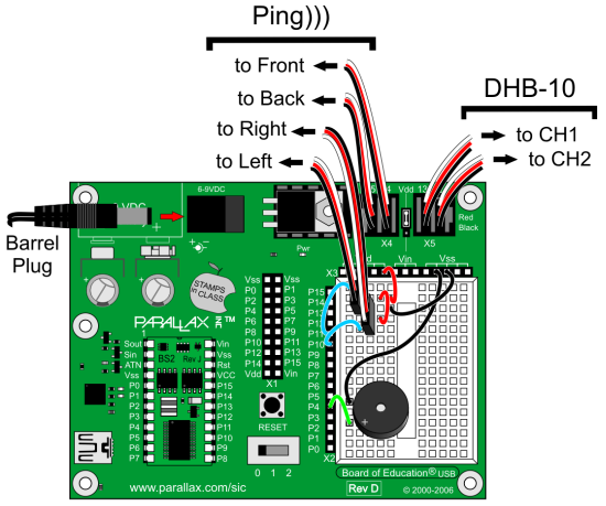
This connection diagram (below) shows where to connect each 3-wire Ping))) sensor cable. If you’re looking at the color version, note that each black wire is connected to either Vss on the breadboard, or the Vss terminal in the servo header (labeled Black to the right of the header block). Each of those black wires should also be connected to a Ping))) sensor’s GND pin. The power jumper between BOE servo ports 13 and 14 should also be set to Vdd.
WARNING! Wiring errors can damage the Ping))) sensors and/or your BASIC Stamp. Do not turn power back on until you have double-checked all the connections in this section’s checklist below.

- Turn all power off before building the circuit.
- Double check to make sure the power jumper between the 14 and 13 servo ports is set to Vdd (5 V).
- Make sure that each 3-wire cable’s black wire is connected to a Ping))) sensor’s GND connection (and red to 5 V and white to SIG).
- On the BOE’s breadboard, make sure that each 3-wire cable’s black wire is connected to Vss, each red wire is connected to Vdd, and each white wire is connected to its corresponding I/O pin, P10 to the right Ping))) sensor, and P11 to the left.
- In the BOE’s servo header, make sure that the front Ping))) sensor is connected to P14 and rear to P15. Then, double check to make sure that all black wires in the servo ports align with the Black label to the right of the servo.
The Debug Terminal display after connecting the Ping))) sensors and running the example program will resemble this. If all the Ping))) sensors are connected correctly, the display should show the centimeter distances of obstacles placed in front of each one (within its 3 cm to 3 m range, and typically +/- 1 cm). Note that right now, the right Ping))) sensor does not see an obstacle, either because it’s beyond the 3 m limit, or the obstacle might be at an angle that’s reflecting the ultrasonic energy away from (instead of back to) the sensor. If you put your hand about 10 cm in front of the right sensor, that value should change to about 10. Make sure that each sensor correctly reports distances when you do that.
- Run Test Ping Array.bs2.
- Use the debug terminal and an obstacle (like your hand) 10 cm from each sensor to verify that each Ping))) sensor correctly reports centimeter distances of obstacles you place in front of them.
- For any Ping))) that doesn’t respond correctly, check the wiring connections.
' Arlo - Test Ping Array

' {$STAMP BS2}                               ' Stamp directive
' {$PBASIC 2.5}                              ' PBASIC directive

n              VAR     Nib                   ' Counting index
pinPing        VAR     Nib                   ' Ping pin variable
tEcho          VAR     Word                  ' Echo time variable
cm             VAR     tEcho                 ' Recycle echo time as cm

DO                                           ' Main loop
  IF n = 0 THEN DEBUG HOME,                  ' If n is 0 then display heading
                "Ping))) Distances", CR,
                "-----------------", CR
  LOOKUP n, [14, 11, 10, 15], pinPing        ' Pick ping pin
  PULSOUT pinPing, 5                         ' Send chirp
  PULSIN pinPing, 1, tEcho                   ' Measure echo time
  cm = tEcho / 29                            ' Echo time to cm distance
  SELECT n                                   ' Pick which ping to display
    CASE 0: DEBUG "Front: "
    CASE 1: DEBUG "Left:  "
    CASE 2: DEBUG "Right: "
    CASE 3: DEBUG "Back:  "
  ENDSELECT
  DEBUG DEC3 cm, " cm", CR                   ' Display distance
  n = n + 1                                  ' Increment index
  IF n >= 4 THEN n = 0                       ' Reset index after last ping
  PAUSE 50                                   ' Wait 50 ms befor repeat
LOOP                                         ' Repeat main loop