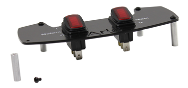
- Next, attach each of the four 1” long standoffs through each of the four holes in the plate using (4) #4-40 x 1/4” long black pan-head screws.
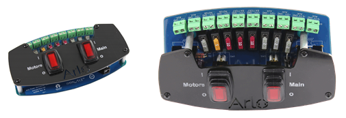
- Before mounting the switch plate to the PDB, we'll install the necessary fuses. The board has labels, but you can reference the right-hand image below as well. With the board oriented so that the terminal blocks are furthest away from you, the fuses should be placed in left to right as follows: 2A, 5A, 10A, 10A, 10A, 2A, 2A, 2A. Double check the placement with the board labels before moving on.
Note: In the two fuse holders marked by the board label "Max 15 Amp Total", you must insert a 5A fuse into one and a 10A fuse into the other. Together they make up the 15A Total indicated by the board label.
- Now, being gentle yet firm, carefully line up the switch connections with the terminals on the PCB and gently “wiggle” the assemblies together such that the standoffs are flat to the PCB.