Building the Circuits and Maze
Circuit
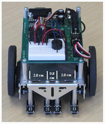
Follow the instructions included with the QTI Line Follower AppKit (#28108) (see Downloads & Resources section of the product page for a digital copy). Some hardware modifications are needed for this application. In the AppKit instructions, each QTI is mounted edge to edge, but in this application, more spacing will be required between the QTIs so the Boe-Bot can detect turns and other obstacles. Use Figure 1 as a guide and mount the QTIs so the two center QTIs are 0.8 cm apart, and the outermost sensors are 2 cm from the center QTIs.
Figure 1 - Mounted QTI Sensors
Maze
Figure 2 shows a maze with a variety of obstacles for the Boe-Bot to navigate, including short and long straight tracks, 90° left and right turns, a T-intersection, and a dead end. These obstacles pose a number of navigation challenges that you can solve, and in doing so, improve your Boe-Bot’s performance in larger and more complex mazes. When constructing your maze, use a large piece of poster board and make sure each lane stripe is 1.5 inches wide of black tape. Figure 2 shows the maze designed for this activity (not to scale).
Figure 2 - Boe-Bot Electrical Tape Maze

Calibration, Calibration, and More Calibration
Before we begin, you should know that the last program in this project may be larger than the example programs you may have tried in Robotics with the Boe-Bot. That’s because there are a lot of conditions that have to be taken into account! This “mini-project” demonstrates how to take a complex problem and break it down into small pieces in order to successfully solve it. To do this, we’re going to have to calibrate our Boe-Bot to maneuver through each condition before putting the whole thing together. This will save us time when troubleshooting if we know that each individual piece works as it should.
Make Sure You Complete Each Calibration Step!
It is very important to follow all calibration instructions with your Boe-Bot and update the values in the code that they determine experimentally. If you skip any steps or try to run the example code as is, it probably will not work.
Keep in mind that the value of the Boe-Bot is that, while fun to play with, it is not a toy robot with a limited set of functions. It is a robot with a prototyping platform that can be whatever you design it to be. That is, if you’re willing to put in a little extra work, and learn a little something!
Moving Forward
Since the Boe-Bot will need to move slowly at some points in the maze, we’ll have to slow down the servos form the normal 850, 650 PUSLOUT durations. This will help ensure that QTI readings aren’t missed as the Boe-Bot navigates through the maze, and you can use the same testing procedure introduced in Robotics with the Boe-Bot Chapter 4, Activity #2.
To slow forward movement, remember that a PULSOUT value of 750 stops the servo motors. So we’ll want to pick values closer to 750 so the Boe-Bot slowly moves forward. For further explanation, take a look at see the Rotational Velocity vs. Pulse Width for Servo graph in Robotics with the Boe-Bot Chapter 3, Activity #4. Notice how the speed only really starts slowing as the pulses approach 700 from 650 and 800 from 850, so don’t worry if the change from 850 to 840 does not appear to have any effect.
Below is an adaptation of BoeBotForwardTenSeconds.bs2, and can be used to calibrate your Boe-Bot.
' SlowlyForward.bs2
' Calibrate your Boe-Bot to slowly move forward in a straight line.

' {$STAMP BS2}
' {$PBASIC 2.5}

counter   VAR    Word

FOR counter = 1 TO 407
  PULSOUT 13, 770
  PULSOUT 12, 730
  PAUSE 20
NEXT

END
90° Left Turn Calibration
Once you’ve got the slow-forward code calibrated, the next step is to calibrate 90° turns. There are a lot of them in the maze, so do a good job here. It’s simple, and you’ve already calibrated your Boe-Bot to complete one in Robotics with the Boe-Bot Chapter 4, Activity #2…right? If not, do not proceed until you are done with this important step! Now all we have to do is program the Boe-Bot to turn left when the maze path does. You can set conditions for the Boe-Bot to follow using SELECT…CASE statements. That way, if the QTIs are sending readings that the tell the BASIC Stamp the Boe-Bot needs to turn left, the BASIC Stamp can then send pulses to the servos to execute a 90° left turn.
Confused?
If you don’t understand SELECT…CASE statements and how they apply here, go back and visit Boe-Bot Line Following with Four QTI Sensors for detailed information on how line-following with QTIs works.
Use the sample code below and adjust the values as necessary so your Boe-Bot executes 90° left turns while staying centered on the maze path.
' MazeNavigation_LeftTurn.bs2
' Boe-Bot turns left based on values from the QTIs.

' {$STAMP BS2}
' {$PBASIC 2.5}

qtis            VAR   Nib                 ' qti black/white states
pulseCount      VAR   Byte                ' FOR..NEXT loop counter for turning

OUTB = %1111                              ' Set OUTB bits to 1

DO                                        ' Main DO...LOOP
  GOSUB Check_Qtis                        ' Get QTI states

  SELECT qtis                             ' Control servo speeds/directions
    CASE %0110                            ' Straight ahead
      PULSOUT 13, 770
      PULSOUT 12, 730
      PAUSE 20
    CASE %1110
      GOSUB Turn_Left
    CASE ELSE                             ' Do nothing
      PAUSE 3
  ENDSELECT
LOOP

Check_Qtis:
' Checks the state of each QTI Sensor. 0 means white surface, 1 means black.
  DIRB = %1111                            ' P7..P4 -> output
  PAUSE 0                                 ' Delay = 230 us
  DIRB = %0000                            ' P7..P4 -> input
  PAUSE 0                                 ' Delay = 230 us
  qtis = INB                              ' Store QTI outputs in INB
RETURN

Turn_Left:
  FOR pulseCount = 0 TO 15                ' Go forward a bit so Boe-Bot
    PULSOUT 13, 770                       ' stays on course
    PULSOUT 12, 730
    PAUSE 20
  NEXT
  FOR pulseCount = 0 TO 24                ' Turn left, about 90-degrees
    PULSOUT 13, 650
    PULSOUT 12, 650
    PAUSE 20
  NEXT
RETURN
90° Right Turn Calibration
Calibrating your Boe-Bot to execute 90° right turns works the same way as calibrating left turns. These values probably won’t be a mirror image of left turns, so it’s important to test and find the necessary PULSOUT duration values to make the right turns as reliable as the left turns. Use the sample code below and adjust the values as necessary so your Boe-Bot executes 90° right turns while staying centered on the maze path.
' MazeNavigation_LeftTurn.bs2
' Boe-Bot turns left based on values from the QTIs.

' {$STAMP BS2}
' {$PBASIC 2.5}

qtis            VAR   Nib                 ' qti black/white states
pulseCount      VAR   Byte                ' FOR..NEXT loop counter for turning

OUTB = %1111                              ' Set OUTB bits to 1

DO                                        ' Main DO...LOOP
  GOSUB Check_Qtis                        ' Get QTI states

  SELECT qtis                             ' Control servo speeds/directions
    CASE %0110                            ' Straight ahead
      PULSOUT 13, 770
      PULSOUT 12, 730
      PAUSE 20
    CASE %0111
      GOSUB Turn_Right
    CASE ELSE                             ' Do nothing
      PAUSE 3
  ENDSELECT
LOOP

Check_Qtis:
' Checks the state of each QTI Sensor. 0 means white surface, 1 means black  DIRB = %1111                        ' P7..P4 -> output
  PAUSE 0                                 ' Delay = 230 us
  DIRB = %0000                            ' P7..P4 -> input
  PAUSE 0                                 ' Delay = 230 us
  qtis = INB                              ' Store QTI outputs in INB
RETURN

Turn_Right:
  FOR pulseCount = 0 TO 15                ' Go forward a bit so Boe-Bot
    PULSOUT 13, 770                       ' stays on course
    PULSOUT 12, 730
    PAUSE 20
  NEXT
  FOR pulseCount = 0 TO 24                ' Turn right, about 90-degrees
    PULSOUT 13, 850
    PULSOUT 12, 850
    PAUSE 20
  NEXT
RETURN
T-Intersection Calibration
Alright, now what happens when the Boe-Bot encounters a T-Intersection? One solution, which we will use here, is to program the Boe-Bot to make a random decision when it reaches the T-Intersection. We can do this by generating a pseudo-random number, and then turn left or right based a single bit of that random number (0 or 1).
In MazeNavigation_TIntersection.bs2, a pseudo-random number ranging from 0 to 65535 is generated each time through the Main loop using the RANDOM command. By looking at a single bit of that number, the Boe-Bot can turn left or right depending if the value of that bit is 0 or 1.
Why use the RANDOM command in the Main loop and not in the T_Intersection subroutine?
Each time the RANDOM command is used, it creates a pseudo-random number. This means that even though the number generated appears random, it is aaaactually generated by a logic operation using the initial value (the “seed”) in the variable named rng to “tap” into a sequence of 65535 essentially random numbers. So, if the command RANDOM rng was placed in the T_Intersection subroutine, the same value of rng would be used, generating the same sequence of values each time. However, by putting this command in the Main routine, the value of rng will change each time through the loop, producing a more desirable set of pseudo-random numbers.
For more information, look up the RANDOM command in the BASIC Stamp Syntax and Reference Manual or the BASIC Stamp Editor Help.
Using MazeNavigation_TIntersection.bs2, complete the following tests:
- Run the code, and use the Debug Terminal to verify that you get pseudo random results each time.
- Press the reset button and move the Boe-Bot along a straight track until it reaches a T-intersection
- Repeat this process several times and verify that the turn results vary each time the T-intersection is reached.
' MazeNavigation_TIntersection.bs2
' When all QTI sensors detect a black line, the Boe-Bot randomly decides to
' turn left or right.  This codes simulates the decision by printing "Turn
' Left!” or "Turn Right!" to the debug terminal.

' {$STAMP BS2}
' {$PBASIC 2.5}


rng             VAR   Word                ' random number
turnDecision    VAR   rng.BIT0            ' Bit0 of the random number
qtis            VAR   Nib                 ' qti black/white states

OUTB = %1111                              ' Set OUTB bits to 1
DEBUG CLS                                 ' Clear the Debug screen

DO                                        ' Main DO...LOOP
  GOSUB Check_Qtis                        ' Get QTI states
  RANDOM rng                              ' Create random number

  SELECT qtis                             ' Control servo speeds/directions
    CASE %0110                            ' Straight ahead
      PULSOUT 13, 770
      PULSOUT 12, 730
      PAUSE 20
    CASE %1111
      GOSUB T_Intersection
    CASE ELSE                             ' Do nothing
      PAUSE 3
  ENDSELECT
LOOP

Check_Qtis:
' Checks the state of each QTI Sensor. 0 means white surface, 1 means black
  DIRB = %1111                            ' P7..P4 -> output
  PAUSE 0                                 ' Delay = 230 us
  DIRB = %0000                            ' P7..P4 -> input
  PAUSE 0                                 ' Delay = 230 us
  qtis = INB                              ' Store QTI outputs in INB
RETURN

T_Intersection:
  IF (turnDecision = 0) THEN
    DEBUG "Turn Right!", CR
    PAUSE 100
  ELSEIF (turnDecision = 1) THEN
    DEBUG "Turn Left!", CR
    PAUSE 100
  ENDIF
RETURN
Dead End Navigation and ‘Artificial Intelligence’
The dead end is another common maze obstacle, and there are a lot of different approaches to solve this problem. The program below handles it in the following way: the Boe-Bot will back up until it reaches the turn that led to the dead end, and then it will execute a 90° turn to get back on the maze path.
But what then? The Boe-Bot still made another turn that brought it to the dead end, and if it makes that turn again, it will return to start instead of continuing to the end. One way to solve this problem would be to create a new variable. Let’s call it “AI”. When this variable is equal to 1, the Boe-Bot will ignore the left turn that would take it back to Start. By creating a new subroutine named AI_Decision the Boe-Bot can execute left turns based on the value of the AI variable.
Use the following code to verify that your Boe-Bot can successfully navigate its way out of a dead end. Remember, some tweaking may be required!
' MazeNavigation_DeadEnd.bs2
' Boe-Bot backs up until it notices a turn and then moves forward again.

' {$STAMP BS2}
' {$PBASIC 2.5}

qtis            VAR   Nib                 ' qti black/white states
AI              VAR   Byte                ' "Artificial Intelligence"
                                          ' remembers dead ends
pulseCount      VAR   Byte                ' FOR..NEXT loop counter for turning

OUTB = %1111                              ' Set OUTB bits to 1

DO                                        ' Main DO...LOOP
  GOSUB Check_Qtis                        ' Get QTI states

  SELECT qtis                             ' Control servo speeds/directions
    CASE %0110                            ' Straight ahead
      PULSOUT 13, 770
      PULSOUT 12, 730
      PAUSE 20
    CASE %1110
      GOSUB AI_Decision
    CASE %0000                            ' Back-up until it sees another turn
      GOSUB Dead_End
    CASE ELSE                             ' Do nothing
      PAUSE 3
  ENDSELECT
LOOP

Check_Qtis:
' Checks the state of each QTI Sensor. 0 means white surface, 1 means black
  DIRB = %1111                            ' P7..P4 -> output
  PAUSE 0                                 ' Delay = 230 us
  DIRB = %0000                            ' P7..P4 -> input
  PAUSE 0                                 ' Delay = 230 us
  qtis = INB                              ' Store QTI outputs in INB
RETURN

AI_Decision:
  IF (AI = 1) THEN                        ' If AI = 1, Boe-Bot was in dead end
    AI = 0                                ' Set AI variable to 0
    GOSUB Ignore_Turn                     ' Ignore turn that leads to Start
  ELSEIF (AI = 0) THEN                    ' If AI = 0, Boe-Bot was not in
    GOSUB Turn_Left                       ' dead end, so it's OK to turn left.
  ENDIF
RETURN

Ignore_Turn:
  FOR pulseCount = 0 TO 50
    PULSOUT 13, 770
    PULSOUT 12, 730
    PAUSE 20
  NEXT
RETURN

Turn_Left:
  FOR pulseCount = 0 TO 15                ' Go forward a bit so Boe-Bot stays
    PULSOUT 13, 770                       ' on course.
    PULSOUT 12, 730
    PAUSE 20
  NEXT
  FOR pulseCount = 0 TO 17                ' Turn left, about 90-degrees
    PULSOUT 13, 650
    PULSOUT 12, 650
    PAUSE 20
  NEXT
RETURN

Dead_End:
  DO
    GOSUB Check_Qtis
    PULSOUT 13, 730
    PULSOUT 12, 770
    PAUSE 20
  LOOP UNTIL (qtis = %0111)

  IF (qtis = %0111) THEN
    PAUSE 20
    FOR pulseCount = 0 TO 15
      PULSOUT 13, 770
      PULSOUT 12, 730
      PAUSE 20
    NEXT
    FOR pulseCount = 0 TO 17
      PULSOUT 13, 850
      PULSOUT 12, 850
      PAUSE 20
    NEXT
  ENDIF
  AI = 1
RETURN
Keep the Boe-Bot on Track!
The final calibration step will be to write code that keeps the Boe-Bot centered on the electrical tape, since there are several factors that could knock it off course: the tape not being perfectly straight, slippage during turns, etc. Keep in mind that line correction can be difficult when navigating through mazes, since there are a lot of different ways that the Boe-Bot can move off track, and each response would be different. In the solution below, whenever the Boe-Bot detects that it has gone off course, it responds as follows:
- Stop.
- Slowly rotate until both middle sensors are back on the line.
- Turn slightly left/right depending which way the Boe-Bot went off track.
- Turn in the other direction slightly to center the Boe-Bot back on the line.
This code was taken through several iterations of calibration, testing, recalibration, re-testing, etc. Since the values may be completely different you may also have to go through several iterations of test and recalibrate. Keep in mind that these steps are essential for successful line following though the maze, since the center sensors need to be on the line when moving forward. Use the following steps to make sure the Boe-Bot can stay centered on the maze path:
- Start with the far left sensor on the electrical tape and see how long it takes the Boe-Bot to center itself on the line.
- If you find that the Boe-Bot doesn’t correct fast enough, try increasing the pulseCount durations in the FOR...NEXT loops.
- On the other hand, if you find the Boe-Bot turns too far, try decreasing the pulseCount durations in the FOR…NEXT loops.
- Repeat with the far right sensor, far left and mid left sensors, and far right and mid right sensors.
- Once those values seem OK, try sliding the poster board to force the Boe-Bot to go off track and see how quickly it reacts.
' MazeNavigation_StayOnStripe.bs2
' Calibration program to keep the Boe-Bot on the electrical tape path.

' {$STAMP BS2}
' {$PBASIC 2.5}

qtis          VAR     Nib                 ' qti black/white states
pulseCount    VAR     Word                ' FOR...NEXT loop counter for smooth
                                          '  turning.
OUTB = %1111                              ' Set OUTB bits to 1

DO                                        ' Main DO...LOOP
  GOSUB Check_Qtis                        ' Get QTI states

  SELECT qtis                ' Control servo speeds/directions
    CASE %0110               ' Mid Left and Right sensors detected, go forward
      PULSOUT 13, 770
      PULSOUT 12, 730
      PAUSE 20
    CASE %1000                            ' Far Left sensor detected
      GOSUB BackOnTrack_OneSensorLeft
    CASE %1100                            ' Far and Mid Left sensors detected
      GOSUB BackOnTrack_TwoSensorsLeft
    CASE %0001                            ' Far Right sensor detected
      GOSUB BackOnTrack_OneSensorRight
    CASE %0011                            ' Far and Mid Right sensor detected
      GOSUB BackOnTrack_TwoSensorsRight
    CASE ELSE                             ' Do nothing
      PAUSE 3
  ENDSELECT
LOOP

Check_Qtis:
' Checks the state of each QTI Sensor. 0 means white surface, 1 means black
  DIRB = %1111                            ' P7..P4 -> output
  PAUSE 0                                 ' Delay = 230 us
  DIRB = %0000                            ' P7..P4 -> input
  PAUSE 0                                 ' Delay = 230 us
  qtis = INB                              ' Store QTI outputs in INB
RETURN

BackOnTrack_OneSensorLeft:
  PULSOUT 13, 750                         ' Stop
  PULSOUT 12, 750
  DO                                      ' Slowly rotate until the middle
    GOSUB Check_Qtis                      ' QTIs are back on the line
    PULSOUT 13, 750
    PULSOUT 12, 740
    PAUSE 20
  LOOP UNTIL (qtis = %0110)

  IF (qtis = %0110) THEN                  ' When the middle QTIs are back
    FOR pulseCount = 1 TO 20              ' on the line, rotate left for
      PULSOUT 13, 750                     ' 20 pulses and then rotate right
      PULSOUT 12, 740                     ' for 10 pulses to center the Boe-
      PAUSE 20                            ' Bot on the line.
    NEXT
    FOR pulseCount = 0 TO 10
      PULSOUT 13, 770
      PULSOUT 12, 750
      PAUSE 20
    NEXT
  ENDIF
RETURN

BackOnTrack_TwoSensorsLeft:
  PULSOUT 13, 750                         ' Stop
  PULSOUT 12, 750
  DO
    GOSUB Check_Qtis                      ' Slowly rotate until the middle
    PULSOUT 13, 750                       ' QTIs are back on the line
    PULSOUT 12, 740
    PAUSE 20
  LOOP UNTIL (qtis = %0110)

  IF (qtis = %0110) THEN                  ' When the middle QTIs are back
    FOR pulseCount = 1 TO 20              ' on the line, rotate left for
      PULSOUT 13, 750                     ' 20 pulses and then rotate right
      PULSOUT 12, 730                     ' for 10 pulses to center the Boe-
      PAUSE 20                            ' Bot on the line.
    NEXT
    FOR pulseCount = 0 TO 10
      PULSOUT 13, 770
      PULSOUT 12, 750
      PAUSE 20
    NEXT
  ENDIF
RETURN

BackOnTrack_OneSensorRight:
  PULSOUT 13, 750                         ' Stop
  PULSOUT 12, 750
  DO
    GOSUB Check_Qtis                      ' Slowly rotate until the middle
    PULSOUT 13, 760                       ' QTIs are back on the line
    PULSOUT 12, 750
    PAUSE 20
  LOOP UNTIL (qtis = %0110)

  IF (qtis = %0110) THEN                  ' When the middle QTIs are back
    FOR pulseCount = 1 TO 20              ' on the line, rotate right for
      PULSOUT 13, 760                     ' 20 pulses and then rotate left
      PULSOUT 12, 750                     ' for 10 pulses to center the Boe-
      PAUSE 20                            ' Bot on the line.
    NEXT
    FOR pulseCount = 0 TO 10
      PULSOUT 13, 750
      PULSOUT 12, 730
      PAUSE 20
    NEXT
  ENDIF
RETURN

BackOnTrack_TwoSensorsRight:
  PULSOUT 13, 750                         ' Stop
  PULSOUT 12, 750
  DO
    GOSUB Check_Qtis                      ' Slowly rotate until the middle
    PULSOUT 13, 760                       ' QTIs are back on the line
    PULSOUT 12, 750
    PAUSE 20
  LOOP UNTIL (qtis = %0110)

  IF (qtis = %0110) THEN                  ' When the middle QTIs are back
    FOR pulseCount = 1 TO 20              ' on the line, rotate right for
      PULSOUT 13, 770                     ' 20 pulses and then rotate left
      PULSOUT 12, 750                     ' for 10 pulses to center the Boe-
      PAUSE 20                            ' Bot on the line.
    NEXT
    FOR pulseCount = 0 TO 10
      PULSOUT 13, 750
      PULSOUT 12, 730
      PAUSE 20
    NEXT
  ENDIF
RETURN