Follow the steps below to build your Boe-Bot robot chassis.
Step 1: Mount the Topside Hardware
(1) robot chassis
(4) 1″ standoffs
(4) pan-head screws, 1/4″ 4-40
(1) rubber grommet, 13/32″

- Insert the 13/32″ rubber grommet into the hole in the center of the chassis. The groove on the edge of the grommet sits over the metal edge of the hole.
- Use the 1/4″ screws to attach the standoffs to the top of the chassis near each corner, as shown.
Step 2: Remove the Servo Horns
(2) Parallax continuous rotation servos.
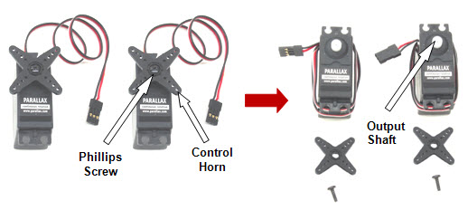
- Use a Phillips screwdriver to remove the screws that hold the servo control horns on the output shafts.
- Pull each horn upwards and off the servo output shaft.
- Save the little screws; you will need them again soon.
Step 3: Mount the Servos on the Chassis
(1) Boe-Bot Chassis, partially assembled.
(2) Parallax continuous rotation servos
(8) pan Head Screws, 3/8″ 4-40
(8) nuts, 4-40
masking tape
pen
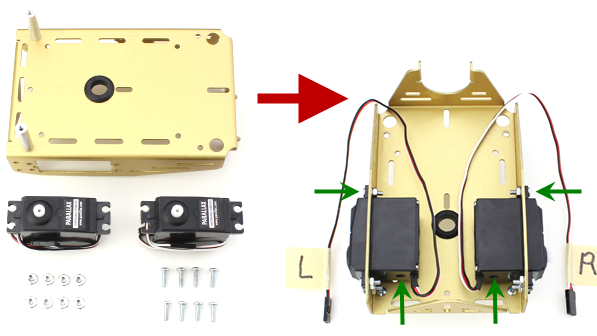
- Slide the servos into the chassis. Look at the little arrows: the servo's mounting tabs set outside, and the little holes in the servo case are facing the triangle end of the chassis.
- Attach the servos to the chassis using the Phillips screws and nuts.
- Use pieces of masking tape to label the servos left (L) and right (R), as shown.
Step 4: Battery Pack
(2) flat-head Phillips screws, 3/8″ 4-40
(2) nuts, 4-40
(1) 4-cell battery pack with 2.1 mm center-positive plug
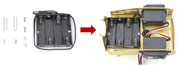
- Insert the battery pack inside the chassis positioned as shown in the picture below.
- Insert flat-head screws from inside the battery pack, and secure them in place with the 4-40 nuts and tighten securely.
- Add batteries to the battery pack.
Step 5: Cords and Wheels
(1) 1/16″ cotter pin
(1) tail wheel ball
(2) rubber band tires
(2) plastic machined wheels
(2) screws saved when removing the servo horns

- Pull the servo cords and battery pack cord up through the grommet hole in the center of the chassis.
- Line up the hole in the tail wheel with the holes in the tail portion of the chassis.
- Run the cotter pin through all three holes (chassis left, tail wheel, chassis right).
- Bend the ends of the cotter pin apart so that it can’t slide back out of the hole.
- Press each plastic wheel onto a servo output shaft until it sinks into the wheel's recess, then secure with the saved servo screws.
- Stretch each rubber band tire and seat it on the outer edge of each wheel.
Step 6: Mount the BASIC Stamp onto the Board of Education
The brain of your robot is a tiny computer called the BASIC Stamp microcontroller.

The BASIC Stamp plugs into the Board of Education development board. It lets you easily connect the BASIC Stamp to:
- a computer cable so you can send programs to the BASIC Stamp
- a battery pack to supply power
- servo motors that will drive the robot
- circuits you will build on the white grid, called a breadboard
Mount the Board of Education to the Boe-Bot's standoffs as shown, using (4) 4-40 pan head screws.
- Place the board on top of the standoffs, so that the white breadboard is close to the large wheels.
- Use the screws to attach the board to the standoffs at each corner.