Build the Circuits
- Follow instructions in your XBee adapter documentation for assembling the adapter and socketing the XBee.
- Build Memsic2125 and XBee circuits on each HomeWork Board tilt controller.
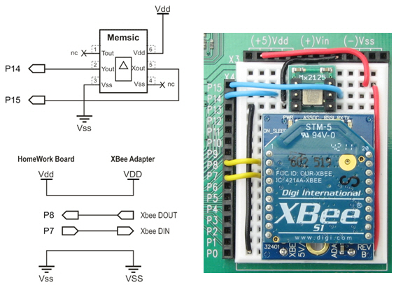
Schematic and Wiring for Tilt Controller
- As with the controller, follow instructions in your XBee adapter documentation for assembling the adapter and socketing the XBee.
- Build the XBee Receiver circuit on each SumoBot or Boe-Bot.
Schematic and Wiring for SumoBot
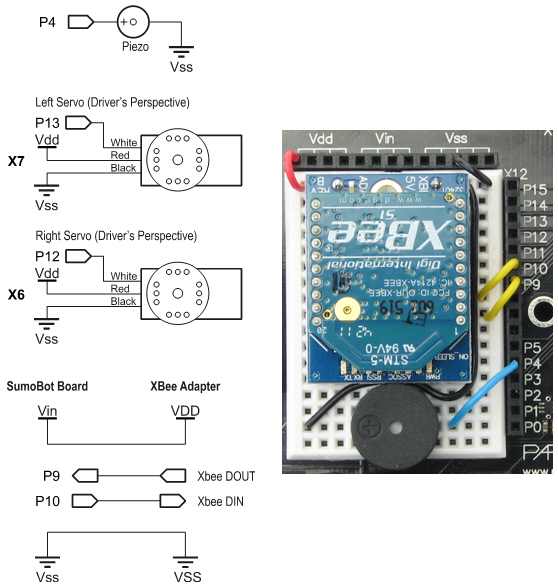
Note: The current photo shows SumoBot Vdd connected to XBee adapter VDD. It needs to be updated to show SumoBot Vin connected to XBee adapter VDD. Although the Vin = 6 V supply exceeds the XBee adapter's stated input range by 1 V, its voltage regulator can handle it. The benefit is that it adds some headroom to prevent supply voltage fluctuations (like when the motors stall during a SumoBot competition) from causing a brownout condition for the XBee.
Test the Accelerometer
Let's make sure your accelerometer is wired correctly first.
- Use your BASIC Stamp Editor software to load Test Accelerometer.bs2 into one of your HomeWork boards.
- Watch the Debug Terminal as you tilt your board in various directions. Hold it level and both x and y values should be in the 2500 range. Tilt it left/right, and the y axis values should vary. The more you tilt, the further your measurements will vary from 2500. In one direction down to about 1875, and up to about 3125 in the other direction. The x axis should vary the same way as you tilt it either toward or away from you. If it doesn't, check your wiring and try again.