One of the standard warnings on many electronic gadgets is that opening the case voids the manufacturer’s warranty. This has discouraged many users from hacking, or making creative modifications to a device. But, it has served as a dare to others to boldly void the warranty and hack away!
Luckily, hacking the S3 is not discouraged but is instead encouraged. To support and encourage hacking, the S3 includes an exposed and labeled Hacker Port. HACK away! As Parallax President Ken Gracey says, “If you can’t hack it, you don’t own it!”
First let’s find the Hacker Port and then look at the pins made available for us to use. Then, let's try connecting two different circuits to the Hacker Port: an LED, and then a rear bumper.
Parts Required
- (1) Yellow LED (#350-00007)
- (1) 3-wire female-female extension cable, 8-inch (#800-00080)
- (1) 220 ohm resistor (red-red-brown) (#150-02210)
- (1) 10 k-ohm resistor (brown-black-orange) (#150-01030)
- Jumper wires (#800-00016)
Other household items needed are listed with each circuit below.
Did You Know?
The term hacker first appeared in the 1960s. It was used to describe a programmer or someone who hacked or modified computer code (oftentimes to cause harm to the computer or its users). Today the term is used more broadly, including to describe someone who has an advanced understanding of computers, networking, programming, or hardware, but who hacks as a hobby or as a way to improve code, or hardware. A hacker culture has developed among a larger commjunity, called Makers, who create, modify or re-purpose all sorts of things. In our case - robots!
What Exactly Is a Hacker Port?
Roboticists love to hack. We encourage this practice, so we made sure that the S3 Hacker Port is fully exposed and situated right on the top of the robot. Take a look at your S3, or at the labeled diagram of the top part of the shell that is included in your Startup Guide. The Hacker Port is on the left hand side next to the front of the left drive wheel. Inside the port you will see three columns and eight rows of pins. These pins are your direct connection to the powerful inner working of the S3 robot. What is so great about these pins being exposed? You don’t have to open the robot’s case to access them. Adding a peripheral sensor can be as easy as simply plugging in a cable.
Each of these pins has a purpose. To understand the purpose of each pin, engineers create what is called a Pinout diagram. Your Hacker Port label shows pin numbering, supply voltage, and ground connection.
The pinout diagrams for Propeller microcontrollers are very detailed. If you're curious, do an online search for “Parallax Propeller pinout.” You will notice that the Propeller microcontroller has a lot more pins than what is available on our Hacker Port. Many of these, however, are reserved for monitoring and controlling the many built-in sensors and other features of your S3 robot.
Let’s look at this pinout diagram of the S3’s Hacker Port, taken from the S3 User Guide included with your Scribbler.

Let's try doing something useful with a few of the pins in the Hacker Port.
Connect an LED
A diode is an electrical part that only lets electricity flow through it in one direction. A light-emitting diode (LED) emits light when current passes through it. In order for an LED to light up, it must be connected in the correct way. If you plug an LED in backward it will not emit light.
An LED has two terminals: the anode and the cathode. The anode lead, the wide part of the triangle in the schematic symbol, is labeled with the plus-sign (+). The cathode lead, labeled with a minus-sign (-), is the verticle line across the point of the triangle in the schematic symbol.
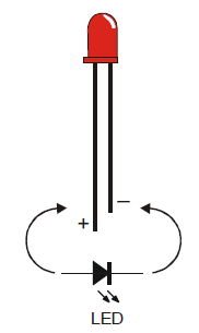
You can tell the anode and cathode apart by the shape of the LED’s plastic case. Look closely - it’s mostly round, but there is a small flat area near the cathode lead. Also note that the LED’s leads are different lengths. Usually, the shorter lead is connected to the cathode.
Always check the LED’s plastic case. Sometimes the leads have been clipped to the same length, or a manufacturer does not follow this convention.
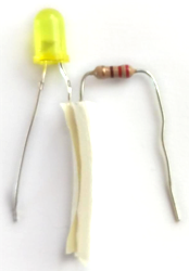
One of the simplest things you can attach to the Hacker Port is an LED. To build an LED circuit for your Scribbler Robot, you will need the items below:
- 3-pin cable
- 220 ohm resistor (red-red-brown)
- Yellow LED
- tape, such as masking tape or electrical tape
Before connecting anything to your Scribbler robot's Hacker Port, make sure your Scribbler is turned off and unplugged from its programming cable!
- Connect the long leg of the LED to one of the legs of the resistor. You can make this connection by simply twisting the legs together until they make a good electrical connection. Then, cover this connection with a small amount of tape.

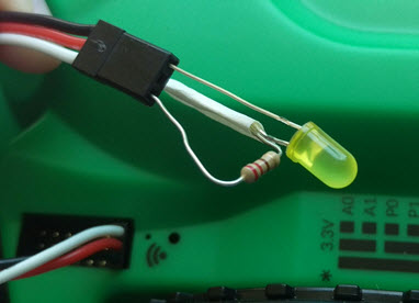
- Insert the unconnected leg of the resistor into the white wire's connection on one end of the 3-pin cable, and insert the short leg of the LED into the black wire's connection of the 3-pin cable.
- Find the P5 row of the Hacker Port and plug in the 3-pin cable - make sure the black wire is connected to the Ground pin and the white wire is connected to the P5 (signal) pin.
- Build the following program using blocks from the HACKER PORT > PINS categories and load it onto your Scribbler Robot:

Your LED should now be blinking!
How it works
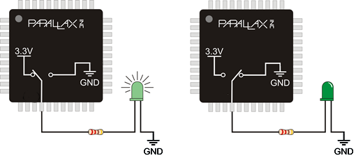
When P5 is turned high by the make pin block, that means it begins sending a positive voltage out of that pin. That positive voltage pushes an electrical current through the resistor and then the LED. Since the LED is connected to Ground, the circuit is completed and the LED glows. When the make pin block sets P5 low, both ends of the circuit are at zero volts, which means there is no voltage to push an electrical current through the LED, which makes it stop glowing.
Build a Rear Bumper
The Scribbler Robot has an infrared obstacle detector in the front, but it has no way to know if it backs into an obstacle. Using a few simple materials, you can add a rear obstacle detector (bumper) to your Scribbler!
You will need:
- (1) 3-pin cable
- 1 large paperclip
- 1 piece of aluminum, tin, or copper foil (approximately 1/2 inch wide by 6 inches long)
- 2 jumper wires
- 1 10 kohm or larger resistor (brown-black-orange)
- masking or duct tape
Make sure your Scribbler robot is turned off before connecting anything to the Hacker Port.
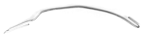
- Bend the large paperclip into the shape shown:
- Tightly twist the exposed end of one jumper wire onto the paperclip. It may help to strip some of the insulation off of the jumper wire to expose more of the bare wire before wrapping it around the paperclip.
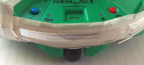
- Tape the foil across the back of the Scribbler robot.
- Poke one end of the other jumper wire through the foil at one end, and tape the connection between the foil and wire down.
- Cover the end of the foil with tape so that the paperclip you are about to tape down on top of it does not make electrical contact with it.

- Tape the paperclip down as shown:
- Insert one leg of the resistor into the white wire's pin, and the other leg into the red wire's pin on the 3-pin cable.
- Insert one jumper wire into the white wire's pin (with the resistor), and the other jumper wire into the black wire's pin on the 3-pin cable.

- Find the P4 row of the Hacker Port, and plug in the 3-pin cable. Make sure the black wire is connected to the ground pin and the white wire is connected to the P4 (signal) pin.
- Build the program shown using the HACKER PORT > PINS > check pin block, and load it to your Scribbler:
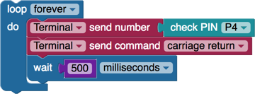
- Observe the terminal output. Press the paperclip so that it makes contact with the foil. If your connections are working properly, the number displayed should change:

How it works
The check pin block sets P4 to an input. This means that it senses when voltage is (or is not) applied to it. The resistor "pulls" the signal pin (white wire) up to a positive voltage so that when the bumper is not pressed, the value of the check pin block will be 1. When the paperclip touches the foil, the signal wire becomes connected directly to ground (0 volts). This means that when the bumper is pressed, the value of the check pin block will be 0.
Try This
- Build the program shown below, and load it to your Scribbler robot:
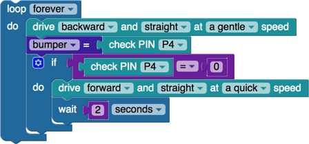
Your Scribbler will drive backward until it bumps into something. Then it will drive forward for 2 seconds before driving backwards again.
Your Turn
- Try using the obstacle sensors in addition to the rear bumper to make your Scribbler robot roam around a room completely on its own.
Special thanks to Parallax friend Whit Stodghill for his assistance in writing, editing, and testing material for these S3 tutorials.