Testing the Right Wheel
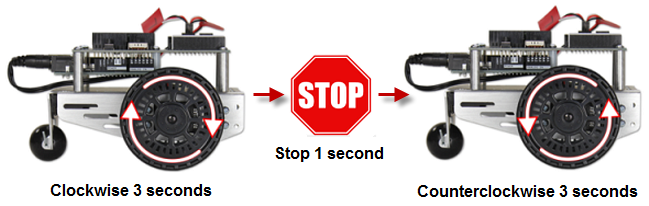
The next example sketch will test the servo connected to the right wheel, shown below. The sketch will make this wheel turn clockwise for three seconds, then stop for one second, then turn counterclockwise for three seconds.
Example Sketch: RightServoTest
- Set the BOE Shield-Bot on its nose so that the drive wheels are suspended above the ground.
- Connect the programming cable and battery pack to the Arduino.
- Enter, save, and upload RightServoTest to your Arduino
- Set the 3-position switch to position-2 and press/release the RESET button.
- Verify that the right wheel turns clockwise for three seconds, stops for one second, then turns counterclockwise for three seconds.
- If the right wheel/servo does not behave as predicted, see the Servo Troubleshooting page.
- If the right wheel/servo does behave properly, then keep going.
/*
 * Robotics with the BOE Shield - RightServoTest
 * Right servo turns clockwise three seconds, stops 1 second, then
 * counterclockwise three seconds.
 */

#include <Servo.h>                           // Include servo library

Servo servoRight;                            // Declare right servo

void setup()                                 // Built in initialization block
{
  servoRight.attach(12);                     // Attach right signal to pin 12

  servoRight.writeMicroseconds(1300);        // Right wheel clockwise
  delay(3000);                               // ...for 3 seconds

  servoRight.writeMicroseconds(1500);        // Stay still
  delay(1000);                               // ...for 3 seconds

  servoRight.writeMicroseconds(1700);        // Right wheel counterclockwise
  delay(3000);                               // ...for 3 seconds

  servoRight.writeMicroseconds(1500);        // Right wheel counterclockwise

}

void loop()                                  // Main loop auto-repeats
{                                            // Empty, nothing needs repeating
}
Your Turn – Testing the Left Wheel
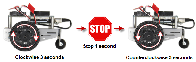
Now, it’s time to run the same test on the left wheel as shown below. This involves modifying the RightServoTest sketch.
- Save RightServoTest as LeftServoTest.
- Change Servo servoRight to Servo servoLeft.
- Change servoRight.Attach(12) to servoLeft.Attach(13).
- Replace the rest of the servoRight references with servoLeft.
- Save the sketch, and upload it to your Arduino.
- Verify that it makes the left servo turn clockwise for 3 seconds, stop for 1 second, then turn counterclockwise for 3 seconds.
- If the left wheel/servo does not behave as predicted, see Servo Troubleshooting.
- If the left wheel/servo does behave properly, then your BOE Shield-Bot is functioning properly, and you are ready to move on to Activity 3: Start-Reset Indicator.