Remember subsystem testing? First, we’ll build the whiskers circuits and write code to check their input states before using them in navigation sketches.
Whisker Circuit and Assembly
- Gather the wisker hardware in the parts list.
- Disconnect power from your board and servos.
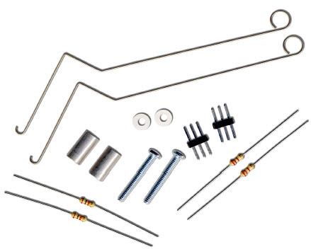
Parts List
(2) whisker wires
(2) 7/8″ pan head 4-40 Phillips screws
(2) ½″ round spacer
(2) nylon washers, size #4
(2) 3-pin m/m headers
(2) resistors, 220 Ω (red-red-brown)
(2) resistors, 10 kΩ (brown-black-orange)
(misc) jumper wires
Building the Whiskers
- Remove the LED circuits that were used as signal monitors while testing the servo navigation.
- Remove the two front screws that hold your board to the front standoffs.
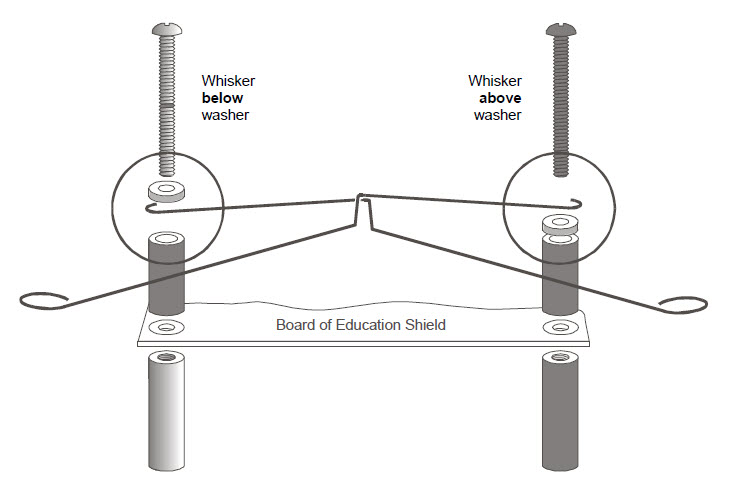
- Thread a nylon washer and then a ½″ round spacer on each of the 7/8″ screws.
- Attach the screws through the holes in your board and into the standoffs below, but do not tighten them all the way yet.
- Slip the hooked ends of the whisker wires around the screws, one above a washer and the other below a washer, positioning them so they cross over each other without touching.
- Tighten the screws into the standoffs.
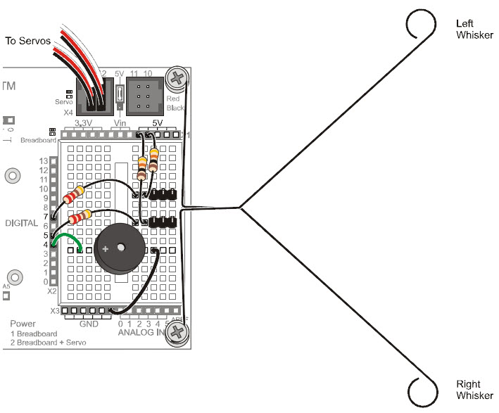
- Use the 220 Ω resistors (red‑red-brown) to connect digital pins 5 and 7 to their corresponding 3-pin headers.
- Use the 10 kΩ resistors (brown-black-orange) to connect 5 V to each 3-pin header.
- Make sure to adjust each whisker so that it is close to, but not touching, the 3-pin header on the breadboard. A distance of about 1/8″ (3 mm) is about right.