The whiskers are connected to ground (Vss) because the plated holes at the outer edge of the board are all connected to Vss. The metal standoffs and screws provide the electrical connection to each whisker.
Since each whisker is connected to digital I/O, the Arduino can be programmed to detect which voltage is applied to each circuit, 5 V or 0 V. First, set each pin to input mode with pinMode(pin, mode), and then detect the pin’s state, HIGH or LOW, with digitalRead(pin) function.
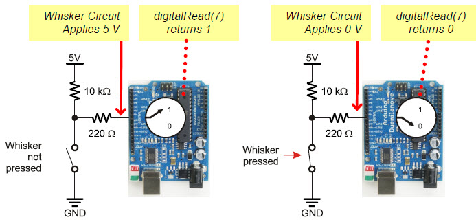
Take a look at the illustrations below. On the left, the circuit applies 5 V when the whisker is not pressed, so digitalRead(7) returns 1 (HIGH). On the right, the circuit applies 0 V when the whisker is pressed, so digitalRead(7) returns 0 (LOW).
Most importantly, your sketch can store the return values in variables, such as wLeft and wRight, and then use them to trigger actions or make decisions. The next example sketch will demonstrate how.
Switch Lingo: Each whisker is both the mechanical extension and the ground electrical connection of a normally open (off until pressed) momentary (on only while pressed) single-pole (one set of electrical contact points), single-throw (only one position conducts) switch.