You may have noticed that brighter car headlights (or a brighter flashlight) can be used to see objects that are further away when it’s dark. By making the BOE Shield-Bot’s infrared LED headlights brighter, you can also increase its detection range. A smaller resistor allows more current to flow through an LED. More current through an LED is what causes it to glow more brightly. In this activity, you will examine the effect of different resistance values with both the red and infrared LEDs.
Parts List:
You will need some extra parts for this activity:
(2) Resistors, 470 Ω (yellow-violet-brown)
(2) Resistors, 220 Ω (red-red-brown)
(2) Resistors, 1 kΩ (brown-black-red)
(2) Resistors, 4.7 kΩ (yellow-violet-red)
Series Resistance and LED Brightness
First, let’s use one of the red LEDs to see the difference that a resistor makes in how brightly an LED glows. All we need to test the LED is a sketch that sends a high signal to the LED.
Example Sketch – P1LedHigh
- Enter, save and upload LeftLedOn.
- Run the sketch and verify that the LED in the circuit connected to P8 emits light.
// Robotics with the BOE Shield - LeftLedOn
// Turn on left LED for brightness testing

void setup()                                 // Built-in initialization block
{
  tone(4, 3000, 1000);                       // Play tone for 1 second
  delay(1000);                               // Delay to finish tone

  pinMode(8, OUTPUT);                        // Left indicator LED
  digitalWrite(8, HIGH);
}

void loop()                                  // Main loop auto-repeats
{
}
Testing LED Brightness with Different Resistors
Remember to disconnect power and the programming cable before you make changes to a circuit. Remember also that the same sketch will run again when you reconnect power, so you can pick up right where you left off with each test.
- Replace the 220 Ω resistor that goes from pin 8 to the right LED’s cathode with a 470 Ω resistor. Note now how brightly the LED glows.
- Repeat for a 1 kΩ resistor.
- Repeat once more with a 4.7 kΩ resistor.
- Replace the 4.7 kΩ resistor with the 220 Ω resistor before moving on to the next portion of this activity.
- Explain in your own words the relationship between LED brightness and series resistance.
Series Resistance and IR Detection Range
We now know that less series resistance will make an LED glow more brightly. A reasonable hypothesis would be that brighter IR LEDs can make it possible to detect objects that are further away.
- Re-open and run TestBothIrAndIndicators.
- Verify that both LED indicator circuits are working properly before continuing.
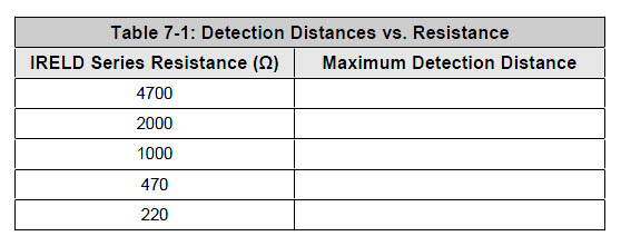
Your Turn – Testing IR LED Range
- With a ruler, measure the furthest distance from the IR LED that a sheet of paper can be detected when using 2 kΩ resistors, and record your data in Table 7‑1.
- Replace the 2 kΩ resistors that connect pin 2 and pin 9 to the IR LED anodes with 4.7 kΩ resistors.
- Determine the furthest distance at which the same sheet of paper is detected, and record your data.
- Repeat with 1 kΩ resistors, 470 Ω resistors, and 220 Ω resistors. (For the smaller resistor values, they may end up making the detectors so sensitive that they see the table surface in front of your robot. If that happens, set the robot on the edge of the table with the IR detectors pointing off the end and try the distance measurements again.)
- Before moving on to the next activity, restore your IR object detectors to their original circuit, with 2 kΩ resistors in series with each IR LED.
- Also, before moving on, make sure to test this last change with TestBothIrAndIndicators to verify that both IR object detectors are working properly.