(2) LEDs – Red
(2) Resistors, 220 Ω (red-red-brown)
(3) Jumper wires
Always disconnect power to your board before building or modifying circuits!
1. Set the BOE Shield’s Power switch to 0.
2. Disconnect the programming cable and battery pack.
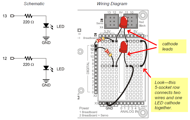
The image below shows the indicator LED circuit schematic on the left, and a wiring diagram example of the circuit built on your BOE Shield’s prototyping area on the right.
The next picture will give you an idea of what is going on when you program the Arduino to control the LED circuit. Imagine that you have a 5 volt (5 V) battery. The Board of Education Shield has a device called a voltage regulator that supplies 5 volts to the sockets labeled 5V. When you connect the anode end of the LED circuit to 5 V, it’s like connecting it to the positive terminal of a 5 V battery. When you connect the circuit to GND, it’s like connecting to the negative terminal of the 5 V battery.
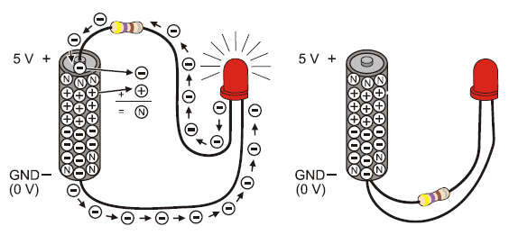
On the left side of the picture, one LED lead is connectd to 5 V and the other to GND. So, 5 V of electrical pressure causes electrons to flow through the circuit (electric current), and that current causes the LED to emit light. The circuit on the right side has both ends of the LED circuit connected to GND. This makes the voltage the same (0 V) at both ends of the circuit. No electrical pressure = no current = no light.
You can connect the LED to a digital I/O pin and program the Arduino to alternate the pin’s output voltage between 5 V and GND. This will turn the LED light on/off, and that’s what we’ll do next.
Volts is abbreviated V.
When you apply voltage to a circuit, it’s like applying electrical pressure. By convention, 5 V means “5 V higher than ground.” Ground, often abbreviated GND, is considered 0 V.
Ground is abbreviated GND.
The term ground originated with electrical systems where this connection is actually a metal rod that has been driven into the ground. In portable electronic devices, ground is commonly used to refer to connections that go to the battery supply’s negative terminal.
Current refers to the rate at which electrons pass through a circuit.
You will often see measurements of current expressed in amps, which is abbreviated A. The currents you will use here are measured in thousandths of an amp, or milliamps. For example, 10.3 mA passes through the circuit shown above.
