It is essential to test the whisker switches before programming your robot to navigate with them. That way, you can be sure the whiskers are sending the right messages. Otherwise, they might be telling the Propeller that they detect something even though they didn't, or vice-versa.
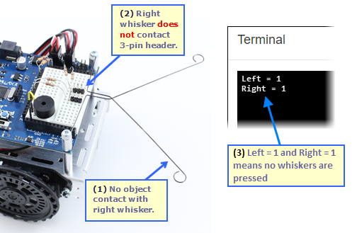
Without pressing any whiskers, the Terminal should display Left = 1 and Right = 1. If either of the numbers is 0, or if either of them flickers between 1 and 0, there is probably a circuit error.
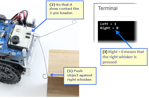
Next, let's check to make sure the Propeller chip detects when the right whisker is pressed or makes contact with an obstacle.
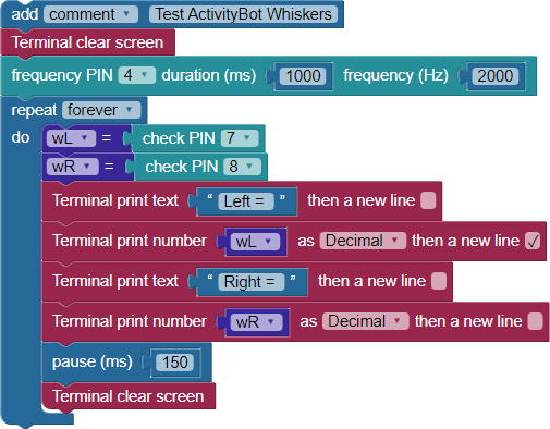
The project starts with a Terminal clear screen block, followed by our "reset indicator" (frequency out) block that beeps the piezospeaker.
After that, the program enters a repeat forever loop. Inside the loop, the first task is to check the state of each I/O pin connected to a whisker circuit - P7 and P8. The value of each state is stored with a Set variable block, wL for the left whisker connected to P7, and wR or the whisker on P8.
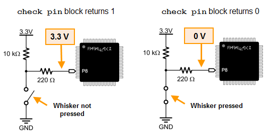
The Propeller I/O pin reads a 1—a "high" signal when the circuit is inactive, that is when the whisker is not being pressed. When the circuit is active as the whisker is being pressed, the Propeller I/O pin reads a 0—a "low" signal.
The next four blocks display the whisker states. A Terminal print text block followed by a Terminal print number block to show each variable and its value. These blocks are followed by a pause (ms) 150, which slows down the loop just enough to let you see the data in the Terminal. A Terminal clear screen block comes last which allows fresh data to be displayed on the next trip through the loop.
Each robot whisker forms a normally-open switch in an active-low circuit with a 10 kΩ pull-up resistor. In its normal, unpressed, inactive state (left), the whisker switch is open - the whisker wire does not touch the 3-pin header post - keeping GND (0 V) out of the circuit. There is no path from GND to P8. So, all we have is 3.3 V on one end of a pair of resistors, and P8 set to input on the other end, sensing 3.3 V and so reporting a high signal (1).
In its active state (left), the pressed whisker switch closes when the wire touches the 3-pin header post. Now P8, through the 220 Ω resistor, 3-pin header, whisker, mounting post, and the mounting hole in the Activity Board, is connected to GND (0 V). P8 set to input senses 0 V, and so reports a low signal (0).
The 10 kΩ resistor in this circuit is called a pull-up resistor. It pulls the voltage at P8 up to 3.3 V when the whisker is not pressed. A pull-up or pull-down resistor applies a voltage that is opposite of the voltage the I/O pin will detect when the switch/button contact is made. Without it, the I/O pin set to input will be more like an antenna, allowing nearby electric fields to affect whether it detects 1 or 0, possibly supplying false data to your project.
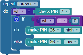
Right now, the Terminal provides visible feedback when each whisker is pressed. That's not very useful for a robot that you want to disconnect from the computer! Let's use the Propeller Activity Board's built-in P26 and P27 LED circuits as whisker indicator lights.