Control a cyber:bot by tilting a micro:bit! The controller micro:bit measures tilt with its accelerometer, and sends that information to the cyber:bot with its radio. The cyber:bot receives the radio transmitted tilt data and uses it to set its wheel speeds.
This tutorial can be approached in two ways:
You will need:
Complete these lessons first from the cyber:bot Tutorial Series: [3]
If you go through the tutorials sequentially, you will gain experience with:
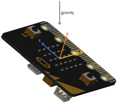
The micro:bit module’s accelerometer has three sensing axes: x, y, and z. You can picture the x axis running side-to-side, the y-axis running front-to-back, and the z axis pointing upwards.
When the micro:bit is held still, the accelerometer can sense how much each of these axes aligns with the downward pull of gravity. This can, in turn, be used to sense how you have tilted the micro:bit. In this activity, you will explore how the various numbers the micro:bit reports for its x and y accelerometer axes relate to its tilt direction and level.
Let's test tilts: level, left, right, toward, and away from you.
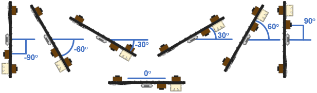
When you vary the tilt angle from left to right, the x-axis accelerometer measurement values vary accordingly.
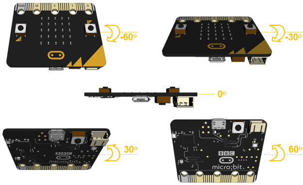
When you vary the tilt angle from facing toward you to facing away from you, the y-axis accelerometer measurement values also vary accordingly.
# test_tilts_intro

from microbit import *

sleep(1000)

while True:
    x = accelerometer.get_x()
    y = accelerometer.get_y()

    print("x =", x, ", y =", y)

    sleep(750)
| Direction | Angle | X | Y |
|---|---|---|---|
| Vertical facing away | 90° | 0 | 1024 |
| Mostly facing away | 60° | ||
| Slightly facing away | 30° | 0 | 512 |
| Level | 0° | ||
| Slightly facing towards you | -30° | ||
| Mostly facing towards you | -60° | ||
| Vertical facing towards you | -90° | ||
| Vertical facing left | 90° | ||
| Mostly tilted left | 60° | 888 | 0 |
| Slightly tilted left | 30° | ||
| Level | 0° | ||
| Slightly tilted right | -30° | ||
| Mostly tilted right | -60° | ||
| Vertical facing right | -90° |
Accelerometer means acceleration meter, but what is acceleration?
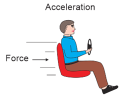
Probably the most common, every-day example is when a car speeds up. During a few seconds of acceleration, a car’s speed might increase from stopped to commute speed. The physics term for this is the change in velocity over time, which is also one definition of acceleration. A car’s speed also changes as it slows down, so that’s acceleration too.
A car speeding up is typically considered positive acceleration, and slowing down is negative acceleration.

Have you ever felt pressed into a seat back as a car accelerates? That’s the feeling of the car seat back applying force to you to make you accelerate in the forward direction. In physics:
force = mass × acceleration
...commonly noted as
F = ma
So, if you know the mass (m) and the force (F), you can calculate an object’s acceleration with a = F / m. That’s essentially what an accelerometer does when it measures acceleration - it measures the force applied to a known mass inside it.
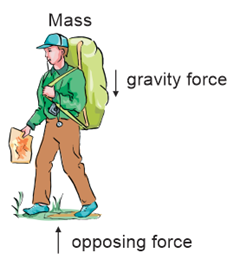
Another force that causes acceleration in nature is gravity (g). Since our bodies have mass, we feel the force of gravity pulling us to the ground. The ground has to push back equally to prevent us from falling through or sinking in.
Newton's second law of motion states that the acceleration of an object is directly
proportional to the applied force and inversely proportional to its mass.
a = F / m
To get from this to F = m×a, multiply both sides of a = F / m by m.
Your mass is all the protons, neutrons, and electrons in your body. Your weight is a measure of how much downward force your feet apply to a scale when you stand on it.
When you weigh yourself on the earth, that’s one value because the earth’s gravity is acting on your mass. If you weighed yourself on the moon, your mass would not change, but your weight would be less. In other words, your body would apply less force on the scale. That’s because the moon has less mass than the earth, so its gravitational pull is weaker.
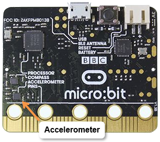
The micro:bit accelerometer is a small chip that senses forces due to gravity and acceleration. It is the NXP/Freescale MMA8652, and it’s located on the bottom of the module, near the lower left corner.
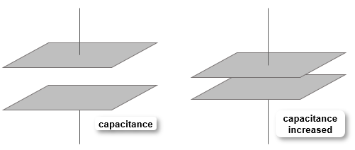
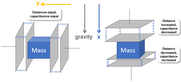
Before talking about how the accelerometer works, remember the capacitor from the cyber:bot visible light sensing activities [4]? Picture the inside of a capacitor as two metal plates separated by an insulator. For example, two plates separated by an insulator have a capacitance—the ability to store charge. If that insulator gets compressed, it brings the two plates closer to each other, and the capacitance increases.
Inside the accelerometer, imagine a tiny object (with mass) held in the middle of a small box. Each wall of the box has capacitors with plates held in place by material that compresses with force. (In the picture, it’s shown as tiny springs.)
When the accelerometer accelerates, the box’s walls have to push on the mass to make it accelerate along with it. As it does so, the tiny springs stretch and compress, changing the distance between the metal plates in each capacitor.
The electronics inside the accelerometer convert that capacitor measurement to a number that reports to the micro:bit when your script executes a statement like x = acceleromter.get_x().
Think about how you speed up when you jump down off of something and land on the ground. That’s the acceleration due to gravity, g. In physics calculations, commonly used values are 32 ft/s² or 9.8 m/s².
The micro:bit won’t typically experience more than 1 g of force from acceleration, unless it’s taking a ride in a high performance model airplane or attached to a wheel that’s spinning really fast. But it does typically experience force equivalent to 1 g of acceleration from gravity’s pull.
These are just concept drawings. The micromachined construction of a proof mass and capacitors inside an actual accelerometer is more elaborate than a simple box with a block inside. It involves a small sliding plate anchored to a flexible material. The plate has capacitive fingers that overlap more or less with metal fingers below it, depending on how much force the plate stretches or compresses the flexible material.
The most common unit accelerometers use is 1 g, which is one unit of gravity. The micro:bit reports gravity/acceleration in steps of 8, from -2048 to + 2048 to report -2 g to 2 g.
If you orient the micro:bit so that the x-axis is pointing down and the y-axis is pointing sideways, the x-axis reports 1024 because it is fully aligned with gravity. The y-axis reports zero because it is not aligned at all.
If you rotate the micro:bit 45° counterclockwise, the measurement of 736 corresponds with the component of the x sensing axis that’s adjacent to gravity.
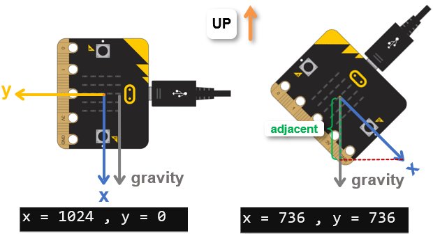
1024 is the ideal value representing 1 g, but your micro:bit might report more or less than that. Also, since it reports accelerometer measurements in steps of 8, if it reports a value like 1040 for 1 g, don’t worry, that’s really only two increments of 8 off from 1024.
The accelerometer methods are part of the microbit module, so no other imports are needed. The instruction sleep(1000) is always recommended at the beginning of any script that prints messages to the terminal. After that, the main loop begins.
# test_tilts_intro

from microbit import *

sleep(1000)

while True:
With the accelerometer held still, a script can get information from each axis about how much it is aligned with gravity. Regardless of whether it’s accelerometer.get_x(), accelerometer.get_y(), or accelerometer.get_z(), the method call returns a value in the range of 1024 to 0 to -1024.
When the measurement is 1024, it means that the accelerometer’s sensing axis is aligned with gravity. As the sensing axis is tilted further out of alignment with gravity, the value decreases. When it’s level (pointing sideways and not at all up or down), the value is zero. As it starts to point away from gravity, the value becomes negative. When it’s aligned with gravity, but pointing the opposite direction, the value is -1024.
    x = accelerometer.get_x()
    y = accelerometer.get_y()
The accelerometer x and y values are printed, and after a 0.75 second pause, the main loop repeats.
    print("x =", x, ", y =", y)

    sleep(750)
The first tilt experiment measured how far the micro:bit tilted away from being held level. The test isolated each axis. So, when you tilted it toward and away from you, there was minimal left/right tilt. So, the y-axis measurements changed while the x-axis measurements only varied slightly. Then, when you tilted it left and right without tipping the micro:bit toward or away from you, the x-axis changed, and the y-axis only varied slightly.
You can also set the micro:bit on its edge, like it’s a wheel. As you rotate it, both the x and y axis measurements will go through their ranges.
If you instead tilt it toward a corner, the x and y axes will return measurements, each indicating the portion of gravity it senses. For example, you might see a measurement like (512, 512). If you balance it on a corner, you might see a measurement like (736, 736). Note that the measurements are different, but their ratios are the same. More about that in the next activity.
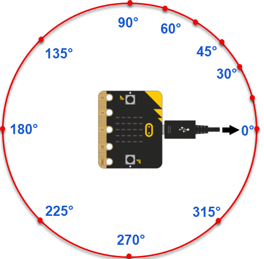
Let’s treat your micro:bit like it’s mounted on a wheel, and watch the x and y values change. In the next activity, you will use a script to calculate the rotation angles.
| Angle | x value | y value |
|---|---|---|
| 0° | 1024 | 0 |
| 45° | ||
| 90° | ||
| 135° | ||
| 180° | ||
| 225° | ||
| 270° | ||
| 315° | ||
| 360° |
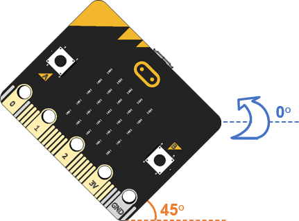
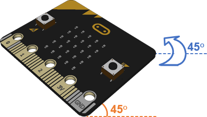
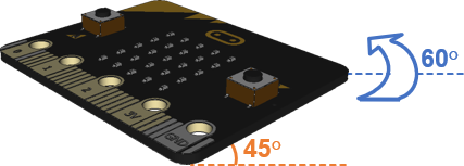
Now, let's try rotation and tilt combined. In this test, you will rotate the micro:bit by a certain angle, and then tilt it away from you by 45°.
| Angle | x value | y value |
|---|---|---|
| 0° | 736 | 0 |
| 45° | ||
| 90° | ||
| 135° | ||
| 180° | ||
| 225° | ||
| 270° | ||
| 315° | ||
| 360° |
Once a script has the x and y tilt values, it can calculate rotation angles.
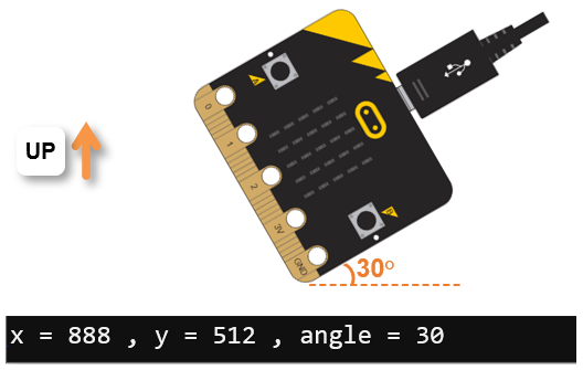
For example, if you hold the micro:bit (or cyber:bot) vertically, and then rotate it 30°, the script can tell you so.
A script can also calculate the overall direction you are tilting the micro:bit, even if you’re not holding it vertically.
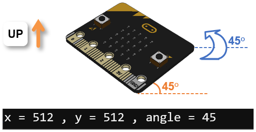
For example, if you rotate it 45° and then tilt it away from you by another 45°, the 45° angle measurement tells you which corner you are tilting it toward. If that angle was 135°, it would mean you are tilting it toward a different corner.
# test_accel_xy_angle

from microbit import *
import math

sleep(1000)

while True:
    x = accelerometer.get_x()
    y = accelerometer.get_y()

    angle = round( math.degrees( math.atan2(y, x) ) )

    print("x =", x, ", y =", y, ", angle =", angle)

    sleep(750)

Are both results close to 1?
See how the x and y values are different for rotated vs. rotated+tilted but the y/x ratios work out to the same?
In addition to the microbit module, this script has to import the math module, which contains common trigonometry methods. Then, sleep(1000) gives the terminal a second to set up communication with the micro:bit before it has to display any messages.
# test_accel_xy_angle

from microbit import *
import math

sleep(1000)
In the main loop, the x and y axis accelerometer measurements are stored in variables named x and y.
while True:
    x = accelerometer.get_x()
    y = accelerometer.get_y()
The next line performs a calculation called arctangent. If you have never heard of it, the next page explains it.
The method call math.atan2(x, y) is what returns the angle result, but that result is in radians—a different kind of angle measurement where a half circle is approximately 3.14, or Pi (π), radians instead of 180°. To convert radians to degrees in Python, use the math.degrees() method.*
angle = round( math.degrees( math.atan2(y, x) ) )
Another way to think about the line above is to break it into steps, each on an individual line. For example:
radians = math.atan2(y, x)
degrees_fp = math.degrees( radians )
angle = round( degrees_fp )
Now that the angle is calculated, the script displays labels for each variable, followed by its value.
    print("x =", x, ", y =", y, ", angle =", angle)

    sleep(750)
*Alternately, the script could multiply by 180 and divide by math.pi. At this point, there’s a floating point result, and the round function will round to the nearest integer. For example, if the result was 179.5 or higher, it would round to 180. If the value was instead between 179 and 179.499…., it would round to 179 instead.
Trigonometry is used to calculate the rotation angle. Even if you haven’t studied it yet, try to follow along. It's pretty neat!
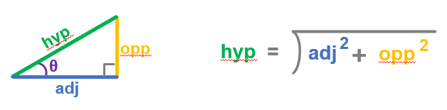
A triangle with a 90° angle (called a right triangle) can have one of its corners marked θ (Greek letter theta) to represent the angle there. Of the right triangle's three sides, the one is opposite of θ, one adjacent to θ forming the right angle, and the hypotenuse is the side that connects the other two. The diagrams will use the shorthand opp, adj, and hyp for these sides.
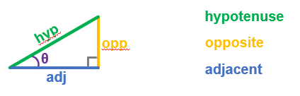
In trigonometry, the ratios of each pair of sides have names: sine (sin), cosine (cos), and tangent (tan). For each angle of θ, the ratio for sin, cos, or tan will be the same, regardless of the size of the triangle. Scientific calculators have sin, cos, and tan keys to complete the division calculation for you, and all you have to do is give it the angle. Python’s math library has methods for calculating these as well.
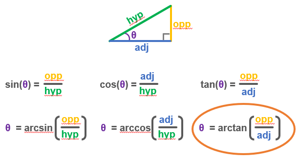
If you only know the result of a division, like opp / adj, you can get the angle θ with the arctan calculation. That’s also called the inverse tangent. Calculators often have tan-1 key for calculating this, and Python’s math module has the atan and atan2 methods.
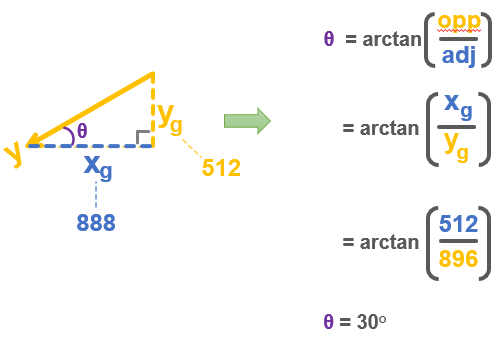
The arctan calculation is particularly useful for calculating the micro:bit’s rotation angle. All your script needs is the amount of gravity acting on the x and y accelerometer axis. Treat the y-axis measurement as the opposite side and the x-axis measurement as the adjacent side of a right triangle, and the arctan calculation will give you the angle θ.
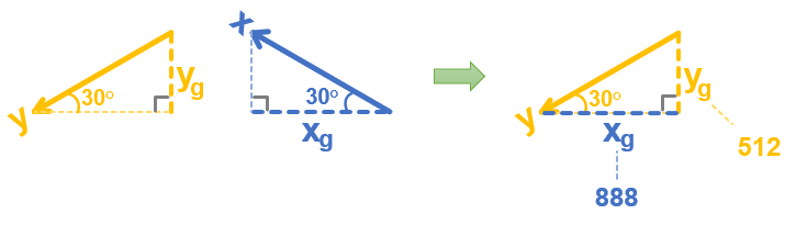
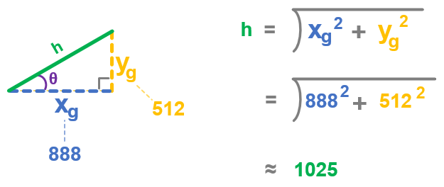
For any angle you rotate to, the micro:bit accelerometer’s x sensing axis will align with gravity by a certain amount (xg), and the y sensing axis will also align by some amount (yg). Let’s say you are holding the micro:bit vertically and have it rotated by 30°. In that case, yg measures about 512, or 0.5 g. (1 g is 1024). xg will be around 888, which is about 0.87 g.

If you look closely, the x and y sensing axis triangles are identical. So, you could take the xg leg from the x-axis triangle and fit it on the adjacent side of the y-axis triangle.
Like the script, if all you know is the x and y axis measurements (xg and yg), you could now use a calculator to figure out the angle θ by taking the arctan of 512 / 888. The result is 29.96, or rounding up, it’s 30.
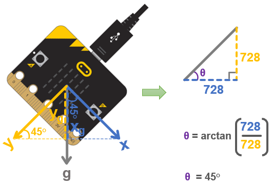
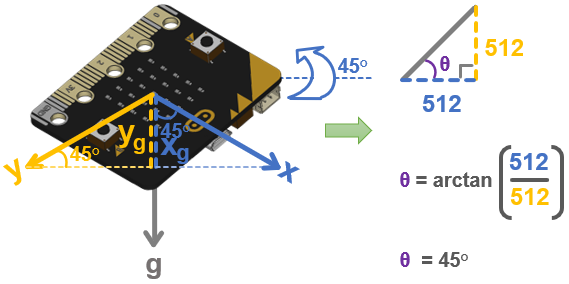
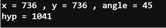
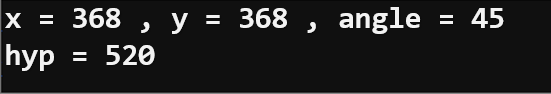
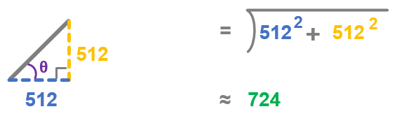
Here is an example where the rotation is 45°. Both x and y report 728, and the arctan(728/728) = arctan(1) = 45.
If you were wondering how the script could calculate the angle even when the micro:bit was tilted, it’s because the portions of the effects on each axis were reduced by the same fraction. When holding vertical, the arctan(728/728) resulted in arctan(1) = 45. Likewise, with the tilt away from you, arctan(512/512) = arctan(1) = 45. In other words, the ratio of the x and y measurements are the same, so the result of the arctan calculation is also the same.
In addition to the rotation angle with opposite and adjacent x and y values, your scripts can calculate the triangle’s hypotenuse to determine how far from vertical the micro:bit has been tilted.
# rotate_angle_with_degree_of_tilt

from microbit import *
import math

sleep(1000)

while True:
    x = accelerometer.get_x()
    y = accelerometer.get_y()

    angle = round( math.degrees( math.atan2(y, x) ) )
    hyp = round( math.sqrt( x**2 + y**2 ) )

    print("x =", x, ", y =", y, ", angle =", angle)
    print("hyp =", hyp)
    print()

    sleep(750)
Tilt it 45° degrees away from you (toward level) while keeping the rotation at 45°. The angle should stay the same, but the hyp variable should report a smaller value.
Continuing to hold the rotation at 45°, tilt it a little further toward level. Did the hyp variable value get even smaller?
The first portion of the code the same as the script test_accel_xy_angle from the previous activity, only the comment at the beginning has a different name!
# rotate_angle_with_degree_of_tilt

from microbit import *
import math

sleep(1000)

while True:
    x = accelerometer.get_x()
    y = accelerometer.get_y()

    angle = round( math.degrees( math.atan2(y, x) ) )
Here is the one line that was added that calculates a number that can be used to indicate the degree of tilt. It calculates x2 + y2, and then takes the square root of that. What it’s calculating is the length of the hypotenuse of the triangles introduced in the previous Did You Know? page on trigonometry [5]. More details are in the next Did You Know? section below.
hyp = round( math.sqrt( x**2 + y**2 ) )
A print statement was added to show the hypotenuse (hyp) result on another line.
    print("x =", x, ", y =", y, ", angle =", angle)
    print("hyp =", hyp)
    print()

    sleep(750)
As you’ve seen with the rotate_angle_with_degree_of_tilt script, the micro:bit can report tilt level along with rotation. But is there really a relationship between the rotation angle and the level of tilt?
The answer is yes. Just as the x-axis measurement is the adjacent leg of the triangle and the y-axis is the opposite leg, the tilt away from vertical is indicated by the hypotenuse.
Here’s an example where the hypotenuse is calculated with the 30° values of xg = 888 and yg = 512. The result is 1025, which is essentially a total of 1g, meaning that the micro:bit is being held vertical.
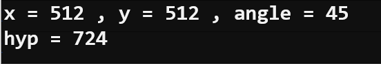
Here is another example where the hypotenuse is calculated with the rotation of 45°, and tilted away at 45°. For this, the values of xg = 512 and yg = 512. The result is 724. The closer the tilt gets to level, the smaller the hypotenuse value will be.
You might encounter this calculation described as a vector magnitude in later physics and engineering classes.
Did you remember that the micro:bit module’s accelerometer also has a z-axis?
Like the hyp calculation from the previous activity, the accelerometer’s z sensing axis can give your script information about the overall level of tilt.
The main advantage of using the z-axis is that it can also tell your script whether the accelerometer is facing up or down. In fact, the hyp calculation is normally only used with two-axis (x-y) accelerometers. Since the micro:bit has a three-axis (x-y-z) accelerometer, scripts can use a combination of atan2(y, x) and z-axis measurements and calculations to get both rotation and tilt level.
In other words, the script can know exactly how the micro:bit is oriented in space.
# test-z-axis-tilt

from microbit import *

sleep(1000)

while True:

    z = accelerometer.get_z()

    print("z =", z)

    sleep(750)
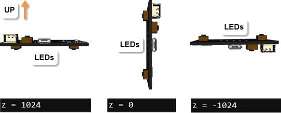
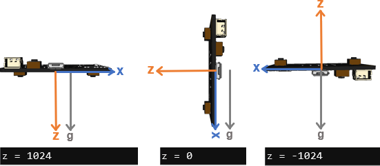
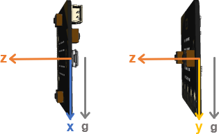
The accelerometer’s z sensing axis aligns with gravity when the micro:bit is held level with its LED display facing down. In that position, accelerometer.get_z() returns a measurement in the -1024 neighborhood.
Held vertically, it returns zero since the z-axis is perpendicular to gravit y— it doesn’t line up at all. If held vertically, rotation angle won’t matter to the z-axis, it still returns zero. Held with the LED display facing up, the z-axis is aligned with gravity again but pointing the opposite direction. Because of that, the accelerometer.get_z() function returns a value near -1024.
As for how the script test-z-axis-tilt works, it is basically the z-axis version of test_tilt_intro [6]. The main difference is that:
    x = accelerometer.get_x()
    y = accelerometer.get_y()

    print("x =", x, ", y =", y)
…has been replaced with
    z = accelerometer.get_z()

    print("z =", z)
Without the z-axis, the x and y tilt with the atan2 calculation from Measure Rotation Angles [7]can give your script information about how the micro:bit has been rotated. By adding the hyp calculation from the previous activity your script can also have information about the degree of tilt, but that information is incomplete. The reason being, it cannot tell if you are facing the LEDs up or down.
The hyp calculation is unable to tell up from down because sqrt(x**2 + y**2) always gives a positive result. That’s because any time you multiply a number by itself, the result is always positive regardless of the number’s sign. For example:
32 = 3 x 3 = 9 -32 = -3 x -3 = 9
For tilt sensing, the accelerometer’s z-axis can complete the picture because the sign is negative for half the range with the LEDs facing up (-1024 to -1) and positive for the other half with the LEDs facing down (-1 to -1024). And of course, it’s zero if it’s neither facing up nor down.
Your script can even use the accelerometer’s z sensing axis to detect how far from level you are holding the micro:bit as you rotate it. For example, if you hold the micro:bit vertical while you rotate it, the z-axis will report zero the whole time. That’s because the z-axis will remain perpendicular to gravity. Some combination of the x- and y-axes will align with gravity and report values, but the z value will stay at zero.
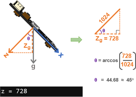
Let’s say that you have tilted the micro:bit as you’ve rotated it. As you saw, a script can use atan2(y, x) to determine the rotation angle, but how far have you tilted it from level? Think of the z-axis measurement as an adjacent leg that aligns with gravity in a triangle. The angle θ between the adjacent leg and the 1 g (1024) hypotenuse can be determined by taking the arccos( zg / 1024).
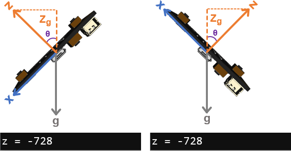
Keep in mind that the z-axis measurement only tells you how far from level the micro:bit is tilted. For example, these two tilts all result in the same z-axis measurement. So, it doesn’t mean that much without more info from the x and y measurements.
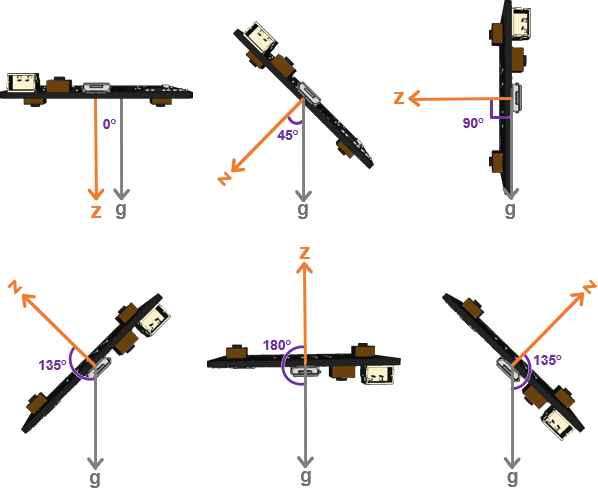
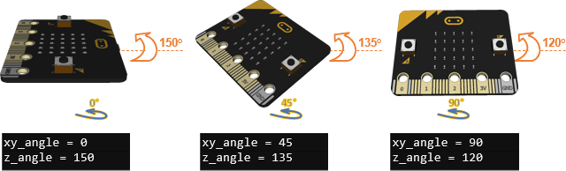
The previous page Did You Know? This Way Up [9] explained how to use arccos to calculate the angle between the micro:bit’s z sensing axis and gravity.
When the LED display is facing straight down, so is the z sensing axis. So the angle between z and gravity is zero.
As the angle between the z-axis and gravity increases, so does the measurement. When the LED display (and z-axis) is facing straight up, it’s angle is 180°. Again, rotating past 180°, the angle decreases, like the last example where it’s back down to 135° again.
# z_axis_degree_of_tilt_try_this

from microbit import *
import math

sleep(1000)

while True:
    z = accelerometer.get_z()

    if z > 1024:
        z = 1024
    elif z < -1024:
        z = -1024

    z_angle = round( math.degrees( math.acos( z/1024) ) )

    print("z =", z, ", z_angle =", z_angle)
    print()

    sleep(750)
| z | z_angle | Direction LEDs are facing |
|---|---|---|
| 1024 | 0 | Straight down |
| 728 | 45 | Half way between straight down and sideways |
| Sideways | ||
| -728 | 135 | Half way between sideways and straight up |
| -1024 | 180 | Straight up |
| Half way past straight up on way to sideways | ||
| Tilted toward you by 45° | ||
| Tilted away from you by 45° | ||
| GND corner tilted down by 45° | ||
| 0 corner tilted down by 45° |
You can combine the xy calculated angle from Measuring Rotation Angles [10] with the z angle introduced here to get a complete picture of how the micro:bit is oriented in space.
Example script: z_axis_and_xy_axis_angles_your_turn
# z_axis_and_xy_axis_angles_your_turn

from microbit import *
import math

sleep(1000)

while True:
    x = accelerometer.get_x()
    y = accelerometer.get_y()
    z = accelerometer.get_z()

    xy_angle = round( math.degrees( math.atan2(y, x) ) )

    if z > 1024:
        z = 1024
    elif z < -1024:
        z = -1024

    z_angle = round( math.degrees( math.acos( z/1024) ) )

    print("z_angle =", z_angle)
    print("xy_angle =", xy_angle)
    print()

    sleep(750)
Micropython's Image.ALL_CLOCKS[hour] list has 12 LED patterns that resemble an analog clock hand at each hour. It can be used for more than timekeeping though. It can also point in the direction you are tilting the micro:bit! This visual feedback will be useful for tilt-controlling the cyber:bot.
First, let’s train an example script that displays each hour hand at 12, 1, 2 and all the way through 11.
# display_clock_positions

from microbit import *

sleep(1000)

while True:

    for hour in range(0, 12):
        print("hour =", hour)
        display.show(Image.ALL_CLOCKS[hour])
        sleep(1000)
It’s important to note that negative hour values display the same way positive hour values do.
Does it cycle twice and respond to a value like -2 the same way it would treat 2?
A script can also make your micro:bit display the angle on its LED display. Here is an example where the needle always points down.
The range of -179…180 has to be split into 12 segments for this to work. For example, we want 0° to map to 3 o’clock. But, we don’t want it to jump to 4 o’clock if it drops to -1. It would be better to have the -15°…14° map to 3 o’clock. Then, 15°…44° can map to 4 o’clock. Likewise, -16°…-45° can map to 2 o’clock.
Here is a clever statement that does all this mapping:
    # Point down

    needle = ( angle + 90 + 15 ) // 30
Here is an example of the steps in the calculation:
Let’s see if -16° really does map to 2 o’clock
Clock values can be from -12 to 11. Any negative value, like -2 is displayed as its positive counterpart, 2 o’clock in this case.
If you want the needle to point up instead, here is the statement to do it. Instead of subtracting 90°, this statement adds 90° to angle. The difference between -90° and 90° is 180 degrees. In other words, the needle points in the opposite direction.
    # Point up

    needle = ( angle + 90 ) + 15 ) // 30
With the tilt direction display mentioned in the Did You Know? section on the previous page, your script can display a needle that either points up or down.
# display_tilt_direction_with_leds

from microbit import *
import math

sleep(1000)

while True:
    x = accelerometer.get_x()
    y = accelerometer.get_y()

    angle = round( math.degrees( math.atan2(y, x) ) )
    needle = ( angle + 90 + 15 ) // 30

    print("angle =", angle, ", needle =", needle)
    display.show(Image.ALL_CLOCKS[needle])

    sleep(200)
needle = ( ( angle + 90 ) + 15 ) // 30
…to a minus sign:
needle = ( ( angle - 90 ) + 15 ) // 30
The next step toward a radio tilt controlled cyber:bot is to radio-transmit those measurements to a receiver.
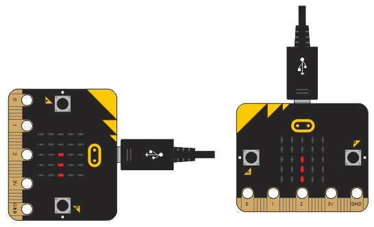
Before adding tilt control statements, it’s important to just make sure all the data is correctly received and processed. So, in this activity, one micro:bit (or cyber:bot) will measure tilt, and display it with both its terminal and LEDs. It will also radio-transmit its x, y, and needle measurements to a cyber:bot.
The cyber:bot will display the measurements it receives in another terminal. It will also mirror the transmitting LED display with its own.
The radio_tilt_transmit_test script is a modified version of display_tilt_down_with_leds with packetizing and transmitting from Cybersecurity: Radio Data’s Send and Receive [11] packets activity. The packet it sends contains x, y, and needle key-value pairs that the receiver will be able to parse and use.
# radio_tilt_transmit_test

from microbit import *
import math
import radio

radio.on()
radio.config(channel=7, queue=1, length=64)

sleep(1000)

while True:
    x = accelerometer.get_x()
    y = accelerometer.get_y()

    angle = round( math.degrees( math.atan2(y, x) ) )
    needle = ( angle + 90 + 15 ) // 30

    print("Send:")
    print("x =", x, ", y =", y, ", needle =", needle)
    print()
    display.show(Image.ALL_CLOCKS[needle])

    dictionary = { }
    dictionary['x'] = x
    dictionary['y'] = y
    dictionary['needle'] = needle

    packet = str(dictionary)
    radio.send(packet)

    sleep(500)
![]()
The radio_tilt_receive_test script is a modified version of countdown_receiver from the Cybersecurity: Radio Data’s Send and Receive Packets [11] activity. To receive and display tilt, it is adjusted to parse x, y, and needle values from the packet it receives, and then use statements from display_tilt_down_with_leds to display the tilt with its LEDs and in the terminal.
For best results:
# radio_tilt_receive_test
from microbit import *
import radio
radio.on()
radio.config(channel=7, queue=1, length=64)
sleep(1000)
while True:
packet = radio.receive()
if packet:
dictionary = eval(packet)
x = dictionary.get('x')
y = dictionary.get('y')
needle = dictionary.get('needle')
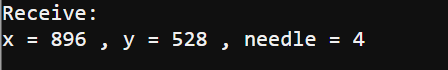
print("Receive:")
print("x =", x, ", y =", y, ", needle =", needle)
print()
display.show(Image.ALL_CLOCKS[needle])
sleep(500)
The goal is to be able to tilt the transmitting micro:bit, and verify matching data in the receive terminal, and on the receiver micro:bit’s LEDs. So, you will be tilting the transmitter while monitoring the receiver.
The script starts with importing modules. Since this script only measures tilt and transmits, it does not need to import the cyberbot module, just the microbit module. It also needs the math module for calculating math.atan2, and the radio module for radio.send.
# radio_tilt_transmit_test

from microbit import *
import math
import radio
After enabling the radio, the script uses radio.config to set the channel, message queue, and message length. As explained in the Cybersecurity: Radio Basics [12] tutorial, the channel defaults to 7, but can be adjusted to an integer from 0 to 83. Classrooms typically assign pairs of students to different channels to avoid crosstalk. The sender and receiver have to be on the same channel for communication to work.
radio.on()
radio.config(channel=7, queue=1, length=64)
The queue is the number of messages the micro:bit can buffer. The default is 3, but reducing it to 1 can save memory. The message length defaults to 32, but it’s better to keep it at 64 to make enough room for longer dictionary strings. By reducing queue from 3 to 1, it saves 128 bytes of memory.
Next, sleep(1000) gives the editor time to establish the serial connection with the micro:bit before it has to display text from the micro:bit.
sleep(1000)
The main loop starts with statements from display_tilt_direction_with_leds that take the accelerometer x and y measurements and calculate/display the LED tilt direction needle. There are extra print statements for "Send:" and an empty line. Since the LEDs display the direction of the tilt like a compass needle, the hour variable’s name is changed to needle here.
while True:
    x = accelerometer.get_x()
    y = accelerometer.get_y()

    angle = round( math.degrees( math.atan2(y, x) ) )
    needle = ( angle + 90 + 15 ) // 30

    print("Send:")
    print("x =", x, ", y =", y, ", needle =", needle)
    print()
    display.show(Image.ALL_CLOCKS[needle])

Next, the x, y, and needle values are added to a dictionary named dictionary.  This step is important because it reduces the work the receiver has to do.  The receiver can just get the values that correspond to the 'x', 'y', and 'needle' keys.
    dictionary = { }
    dictionary['x'] = x
    dictionary['y'] = y
    dictionary['needle'] = needle
After dictionary is populated, all that remains is to convert it to a string, send it through the radio, and delay 0.5 s before repeating the while True loop.
    packet = str(dictionary)
    radio.send(packet)

    sleep(500)
The script starts in much the same way as the radio_transmit_tilt_test. The main difference is that it does not import the math module since it will receive a pre-calculated needle value from the transmitter.
# radio_tilt_receive_test
from microbit import *
import radio
radio.on()
radio.config(channel=7, queue=1, length=64)
sleep(1000)
The main loop starts by copying any data the radio might have received to a variable named packet. When radio.receive() returns none, the script skips everything in the if packet… statement and repeats the while True loop. When radio.receive() returns a string from the transmitter micro:bit, all the statements in the if packet… statement get executed. First, eval(packet) converts the string that was received back to a dictionary. Then dictionary.get calls set the x, y, and needle variables using the 'x', 'y', and 'needle' keys.
while True:

    packet = radio.receive()

    if packet:

        dictionary = eval(packet)

        x = dictionary.get('x')
        y = dictionary.get('y')
        needle = dictionary.get('needle')
Now, that the receiver has variables with the transmitter micro:bit’s measurements, it can display them in the terminal and with the LEDs. As with the transmitter, these statements are similar to what’s in display_tilt_direction_with_leds with extra print statements for "Receive:" and an empty line, the variable for displaying the tilt direction is needle instead of hour.
        print("Receive:")
        print("x =", x, ", y =", y, ", needle =", needle)
        print()

        display.show(Image.ALL_CLOCKS[needle])

        sleep(500)
Now that one micro:bit can radio-transmit tilt info to another, let’s start reducing sleep times and adding statements to make the cyber:bot move based on the tilt data it receives.
To make the tilt controlled robot responsive, it’s important to speed up the while True loop’s repeat rate. The changes are simple, just remove print statements and reduce sleep(500) to sleep(50). This will help prevent delays between tilting the controller and the cyber:bot’s response. Without the print statements, plan to use the LED displays to verify radio communication between the tilt controller and the cyber:bot.
# radio_tilt_transmit_rapid

from microbit import *
import math
import radio

radio.on()
radio.config(channel=7, queue=1, length=64)

sleep(1000)

while True:
    x = accelerometer.get_x()
    y = accelerometer.get_y()

    angle = round( math.degrees( math.atan2(y, x) ) )
    needle = ( angle + 90 + 15 ) // 30

    display.show(Image.ALL_CLOCKS[needle])

    dictionary = { }
    dictionary['x'] = x
    dictionary['y'] = y
    dictionary['needle'] = needle

    packet = str(dictionary)
    radio.send(packet)

    sleep(50)
The radio_tilt_transmit_rapid script is almost identical to radio_tilt_transmit_test from the previous activity. The only differences are that the print statements were removed and the sleep(500) at the end of the loop was changed to sleep(50) to make it more responsive.
Why not just completely remove the sleep call? Probably the most important reason is to not flood the airwaves with unnecessary radio activity. The sleep(50) call reduces the radio transmissions to around 20 times per second. The difference between letting the micro:bit transmit as fast as it can and repeating with a 50 ms pause will not be noticeable as you tilt the micro:bit to make the cyber:bot move.
The radio_tilt_bot_fb_only receiver script has statements added that will make the cyber:bot roll forward and backward based on the y-axis tilt measurement from the transmitter.
For best results, the receiver script should repeat at top speed, so all print and sleep statements have been removed.
# radio_tilt_bot_fb_only

from cyberbot import *
import radio

radio.on()
radio.config(channel=7, queue=1, length=64)

sleep(1000)

while True:

    packet = radio.receive()

    if packet:

        dictionary = eval(packet)

        x = dictionary.get('x')
        y = dictionary.get('y')
        needle = dictionary.get('needle')

        display.show(Image.ALL_CLOCKS[needle])

        fb = y / 10

        vL = fb
        vR = -fb

        bot(18).servo_speed(vL)
        bot(19).servo_speed(vR)
The radio_tilt_bot_fb_only script is also almost identical to radio_tilt_receive_test from the previous activity. One difference is that the sleep(500) was not reduced to 50; it was completely removed. Without the sleep, the receiver script will recheck for radio data at top speed. The only thing limiting the responsiveness is that the transmitter has 50 ms sleep calls, so it’s only transmitting every 20 ms or so.
Some statements were also added to the if… block after the x, y, and needle variables are unpacked.
First fb = y / 10 takes the y tilt value that could hold a value in the -1024 to 1024 range and scales it down to -102 to 102, which is a perfect range for servo control. The fb variable name is shorthand for forward/backward.
fb = y / 10
Next variables for velocity-left (vL) and velocity-right (vR) are set with the value stored in fb. Let’s say you tilt the micro:bit away from you and that the fb value might be around 50. To make the cyber:bot roll forward, vL can be 50, but vR has to be -50 to make the right wheel turn the opposite direction. That’s why vR = -fb.
        vL = fb
        vR = -fb
Now that the vL and vR variables store equal and opposite values based on your y-axis tilt, they can be used to set the left (P18) and right (P19) servo speeds.
        bot(18).servo_speed(vL)
        bot(19).servo_speed(vR)
You might have noticed that it was difficult to hold the tilt transmitting micro:bit to make the cyber:bot stay still. We can fix that by adding a stop range to the tilt values.
The scripts will check if the micro:bit accelerometer’s y-axis is close to zero. The transmitter micro:bit will display a diamond to indicate that it’s nearly level in the forward/backward direction. The receiver script will also make the cyber:bot stay still when the diamond indicator is displayed.
The only thing that needs to be added to the transmitter radio_tilt_transmit_rapid script is an if... block that displays one of two things:
Let’s try it!
# radio_tilt_controller_w_stop_range

from microbit import *
import math
import radio

radio.on()
radio.config(channel=7, queue=1, length=64)

while True:
    x = accelerometer.get_x()
    y = accelerometer.get_y()

    angle = round( math.degrees( math.atan2(y, x) ) )
    needle = ( angle + 90 + 15 ) // 30

    if abs(y) > 80:
        display.show(Image.ALL_CLOCKS[needle])
    else:
        display.show(Image.DIAMOND_SMALL)

    dictionary = { }
    dictionary['x'] = x
    dictionary['y'] = y
    dictionary['needle'] = needle

    packet = str(dictionary)
    radio.send(packet)

    sleep(50)
The radio_tilt_controller_w_stop_range script is just radio_tilt_transmit_rapid with an if…else… statement added.
When the absolute value of y is greater than 80, it displays the tilt direction needle, just like it has up to this point. But, if the y value is anywhere in the -80 to 80 range, it instead displays a small diamond to tell you that your forward/backward tilt is pretty close to level.
    if abs(y) > 80:
        display.show(Image.ALL_CLOCKS[needle])
    else:
        display.show(Image.DIAMOND_SMALL)
The if abs(y) function returns the positive-only version of any value y might store. So, if y stores -20, abs(y) returns 20. If y stores 20, abs(y) doesn’t change anything and just returns 20. So, if abs(y) > 80 is a concise way to check if y is outside the -80…80 range. Another way to check if y is outside that range would be if y > 80 or y < -80.
In addition to displaying the diamond when the y-axis tilt is close to level, the radio_tilt_bot_fb_with_stop_range script also makes the cyber:bot stay still.
# radio_tilt_bot_fb_with_stop_range

from cyberbot import *
import radio

radio.on()
radio.config(channel=7, queue=1, length=64)

while True:

    packet = radio.receive()

    if packet:

        dictionary = eval(packet)
        x = dictionary.get('x')
        y = dictionary.get('y')
        needle = dictionary.get('needle')

        fb = y / 10

        if abs(fb) > 8:
            display.show(Image.ALL_CLOCKS[needle])
            vL = fb
            vR = -fb
        else:
            display.show(Image.DIAMOND_SMALL)
            vL = None
            vR = None


        bot(18).servo_speed(vL)
        bot(19).servo_speed(vR)
While still holding the transmitter micro:bit level, does the cyber:bot stay still?
As you tilt the tilt transmitter away from and then toward you, does it make the cyber:bot roll forward and backward?
Here is the portion of radio_tilt_bot_fb_with_stop_range that’s different from the previous radio_tilt_bot_fb_only that it’s based on.
        if abs(fb) > 8:
            display.show(Image.ALL_CLOCKS[needle])
            vL = fb
            vR = -fb
        else:
            display.show(Image.DIAMOND_SMALL)
            vL = None
            vR = None
Keep in mind that fb is y / 8, so instead of looking for y being outside the +/- 80 range, this program checks if fb is outside the +/- 8 range. When the absolute value of fb is greater than 8, the script displays the tilt needle and sets the vL and vR variables just like it did in the previous radio_tilt_bot_fb_only script. But when fb falls inside the -8 to 8 range, it displays the diamond and sets vL and vR to None.
Whenever the else block sets vL and vR to None, it makes the servos stay still. It’s actually better than setting vL and vR to zero because None causes servo_speed to stop sending control signals. This prevents any slow wheel rotation that might otherwise occur when the servos are slightly out of calibration and the speeds are set to 0.
        bot(18).servo_speed(vL)
        bot(19).servo_speed(vR)
Up to this point, the transmitter and receiver scripts support forward, backward, and stop tilt control.
Adding left/right control will complete the radio tilt controlled cyber:bot functionality. The only modification after this is exception handling for the receiver!
The transmitter micro:bit should still be running the same script from the previous activity. That’s radio_tilt_controller_w_stop_range.
Now for the new cyber:bot receiver script!
# radio_tilt_bot_fb_lr_with_stop_range

from cyberbot import *
import radio

radio.on()
radio.config(channel=7, queue=1, length=64)

while True:

    packet = radio.receive()

    if packet:

        dictionary = eval(packet)

        x = dictionary.get('x')
        y = dictionary.get('y')
        needle = dictionary.get('needle')

        fb = y / 10
        lr = x / 10

        if abs(fb) > 8:
            display.show(Image.ALL_CLOCKS[needle])
            vL = fb
            vR = -fb

            if(fb < 0): lr = -lr
            vL = vL - lr
            vR = vR - lr

        else:
            display.show(Image.DIAMOND_SMALL)

        bot(18).servo_speed(vL)
        bot(19).servo_speed(vR)
| Tilt the micro:bit transmitter | Verify the cyber:bot maneuver |
|---|---|
| Level | Stay still |
| Slightly away from you | Forward slowly |
| Further away from you | Forward faster |
| Slightly toward you | Slowly backward |
| Further toward you | Faster backward |
| Away from you and to the left | Curve forward and to the left |
| Away from you and to the right | Curve forward and to the right |
| Toward you and to the left | Curve backward and to the left |
| Toward you and to the right | Curve backward and to the right |
The radio_tilt_bot_fb_lr_with_stop_range script is just another development step from the previous activity. Here are the changes that were made to radio_tilt_bot_fb_with_stop_range to add the left/right control.
Remember how the script sets fb to y /10 to reduce the range of values from -1024…1024 to -102 to 102? Well, since the x-axis measurements also come in a range of -1024 to 1024, the script can also divide those by 10. That’s what lr = x / 10 does, and lr is shorthand for left/right.
        fb = y / 10
        lr = x / 10                          # <- added

        if abs(fb) > 8:
            display.show(Image.ALL_CLOCKS[needle])
            vL = fb
            vR = -fb
After setting up vL and Vr with fb and -fb, the lr component can be added in to cause turns. The statement if(fb < 0): lr = -lr changes the sign of the lr variable if you are tipping the tilt transmitter toward you. That’s because the rules for wheel rotation directions for turning reverse when the robot is backing up.
            if(fb < 0): lr = -lr             # <- added
            vL = vL - lr                     # <- added
            vR = vR - lr                     # <- added
Let’s try an exercise called variable tracing. Variable tracing is the process of stepping through each line after setting variable values and checking what each statement does with those values. Some software development environments offer an automated version of this, but here, it is a mental exercise to help better understand how the statements correctly control the wheel speeds. The variable values are calculated in comments to the right of the statements.
Example: Tilt the micro:bit away from you and to the left.
Assume the y variable is 400, and the x variable is 200.
x = dictionary.get('x')    # x = 400
y = dictionary.get('y')    # y = 200

fb = y / 10                # fb = 400 / 10 = 40
lr = x / 10                # lr = 200 / 10 = 20

if abs(fb) > 8:            # absolute value fb is greater than 8
    vL = fb                # vL = 40
    vR = -fb               # vR = -40

    if(fb < 0): lr = -lr   # fb is positive so lr stays at 20

    vL = vL - lr           # vL = 40 – 20 = 20
    vR = vR - lr           # vR = -40 – 20 = -60

    bot(18).servo_speed(vL)# vL = 20 left wheel forward slowly
    bot(19).servo_speed(vR)# vR = -60 right wheel forward faster
# result: cyber:bot rolls forward and to the left.
Example: Tilt the micro:bit toward you and to the right.
Assume the y variable is -400, and the x variable is -200.
x = dictionary.get('x')    # x = -400
y = dictionary.get('y')    # y = -200

fb = y / 10                # fb = -400 / 10 = -40
lr = x / 10                # lr = -200 / 10 = -20

if abs(fb) > 8:            # absolute value fb is greater than 8
    vL = fb                # vL = -40
    vR = -fb               # vR = 40

    if(fb < 0): lr = -lr   # fb is negative so lr set to +20

    vL = vL - lr           # vL = -40 – 20 = -60
    vR = vR - lr           # vR = 40 – 20 = 20

    bot(18).servo_speed(vL)# vL = -60 left wheel backward faster
    bot(19).servo_speed(vR)# vR = 20 right wheel backward slower
# result: cyber:bot rolls backward and to the right.
This full version of the tilt control app has exception handling [13] added to the previous script radio_tilt_bot_fb_lr_with_stop_range.
The advantage of using this one is that if another micro:bit is transmitting different messages on the same radio channel, it will be less likely to halt your cyber:bot due to an exception from a packet that doesn’t contain tilt information.
This is the receiver script for your Radio Tilt Controlled cyber:bot. You will also need to load the script on the next page into the tilt controller micro:bit (or cyber:bot) you will use to drive this receiver cyber:bot.
# radio_tilt_controlled_cyberbot

from cyberbot import *
import radio

radio.on()
radio.config(channel=7, queue=1, length=64)

while True:

    packet = radio.receive()

    if packet:

        try:

            dictionary = eval(packet)

            x = dictionary.get('x')
            y = dictionary.get('y')
            needle = dictionary.get('needle')

            fb = y / 10
            lr = x / 10

        except Exception as e:

            display.show(Image.SAD)
            print("Exception e:", e)
            print("Type:", type(e))
            continue

        else:

            if abs(fb) > 8:
                display.show(Image.ALL_CLOCKS[needle])
                vL = fb
                vR = -fb

                if(fb < 0): lr = -lr
                vL = vL - lr
                vR = vR - lr

            else:

                display.show(Image.DIAMOND_SMALL)
                vL = None
                vR = None

        finally:

            bot(18).servo_speed(vL)
            bot(19).servo_speed(vR)
If you came straight here to run the application, this section only explains finishing touches. You can start at the beginning of this tutorial and read through or actually do the activities that introduce one concept at a time and incrementally build the scripts.
The radio_tilt_controlled_cyberbot script started as radio_tilt_bot_fb_lr_with_stop_range from the Add Right/Left Tilt Control [14] activity. Along with How It Works sections in some of the earlier activities, it will allow you to take a closer look at the mechanics of the tilt control app.
As mentioned earlier, exception handling helps prevent other radio messages on the same channel from causing your tilt controlled cyber:bot from throwing an exception in the middle of a maneuver. The only change to the script is that try…except…else… and finally were added at key points, and the code below each was indented. For details on how try…except…else…finally works, read or better still, try the activities in the Exception Handling Primer [13].
Load this application into the micro:bit (or cyber:bot) you want to use as your tilt controller for your cyber:bot that’s running the radio_tilt_controlled_cyberbot script.
The radio_tilt_controller script is just radio_tilt_controller_w_stop_range from Receiver Full Tilt Control & Stop Range [15]. It is repeated here for folks who skip the majority of the tutorial and go directly to running the application.
# radio_tilt_controller

from microbit import *
import math
import radio

radio.on()
radio.config(channel=7, queue=1, length=64)

while True:
    x = accelerometer.get_x()
    y = accelerometer.get_y()

    angle = round( math.degrees( math.atan2(y, x) ) )
    needle = ( angle + 90 + 15 ) // 30

    if abs(y) > 80:
        display.show(Image.ALL_CLOCKS[needle])
    else:
        display.show(Image.DIAMOND_SMALL)

    dictionary = { }
    dictionary['x'] = x
    dictionary['y'] = y
    dictionary['needle'] = needle

    packet = str(dictionary)
    radio.send(packet)

    sleep(50)

Links
[1] https://learn.parallax.com/tutorials/robot/cyberbot/cybersecurity-radio-tilt-control/tilt-radio-tests
[2] https://learn.parallax.com/node/2234
[3] https://learn.parallax.com/tutorials/series/cyberbot-tutorial-series
[4] https://learn.parallax.com/tutorials/robot/cyberbot/visible-light-navigation-cyberbot
[5] https://learn.parallax.com/node/2215
[6] https://learn.parallax.com/tutorials/robot/cyberbot/cybersecurity-radio-tilt-control/measure-accelerometer-tilt/test-tilts
[7] https://learn.parallax.com/tutorials/robot/cyberbot/cybersecurity-radio-tilt-control/measure-tilt-angles/measure-rotation
[8] https://learn.parallax.com/tutorials/robot/cyberbot/cybersecurity-radio-tilt-control/measure-tilt-angles/how-measuring-rotation
[9] https://learn.parallax.com/tutorials/robot/cyberbot/cybersecurity-radio-tilt-control/z-axis-which-way/did-you-know-way
[10] https://learn.parallax.com/tutorials/robot/cyberbot/cybersecurity-radio-tilt-control/measure-rotation-angles/measuring-rotation
[11] https://learn.parallax.com/tutorials/robot/cyberbot/cybersecurity-radio-data/send-and-receive-packets
[12] https://learn.parallax.com/tutorials/robot/cyberbot/cybersecurity-radio-basics
[13] https://learn.parallax.com/tutorials/robot/cyberbot/exception-handling-primer
[14] https://learn.parallax.com/tutorials/cybersecurity-radio-tilt-control/add-leftright-tilt-control
[15] https://learn.parallax.com/tutorials/robot/cyberbot/cybersecurity-radio-tilt-control/adding-stop-range/receiver-full-tilt