Building Circuits on a Breadboard
The white grid on the Board of Education is called a "breadboard." You will use this board to plug in little wires and electronic components to build circuits. How does a breadboard work, and why is it called a breadboard, anyway?
In a moment, you will get to build a circuit on your Boe-Bot's breadboard. Circuits are described with line drawings called "schematics." This video shows you how to look at a schematic and build that circuit on a breadboard.
Ok, now it's your turn. This is about as simple a hardware circuit as we can get.
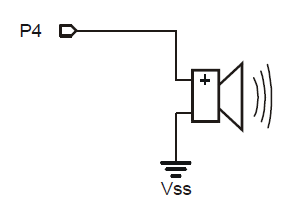
On the left is the schematic symbol for a small "beeper" - a device that will emit a tone when given a series of pulses from an electronic circuit. The right image is what the beeper physically looks like.

This is the schematic diagram of the circuit that we're going to build. It shows the inter-connections of the circuit components. In this case, the "+" side of the beeper is connected to a signal line called "P4" (whose connection is available alongside the breadboard area of the Board of Education)
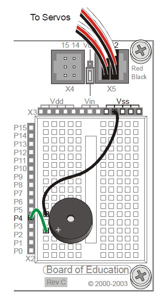
This is a pictorial diagram of what your completed circuit should look like when you're done...
This completes the "hardware" portion of this circuit. However, for anything to happen, we need to introduce some "intelligence" (a program) to cause it to do something...
' {$STAMP BS2}

x VAR Byte

FOR x = 0 TO 20
  HIGH 4
  LOW 4
NEXT

STOP
