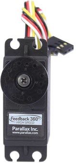
This is the LEGACY VERSION that supports the original ActivityBot with external encoders. If you or your class are entirely using the ActivityBot 360° with Feedback 360° servos that have yellow signal wires like the ones shown below, use the updated Propeller C Programming with the ActivityBot 360° tutorial. [1]
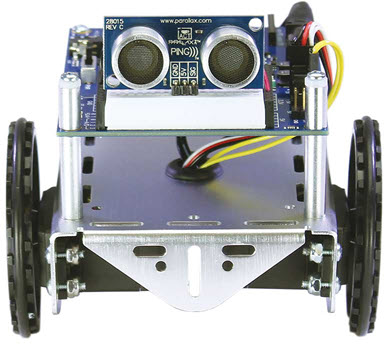
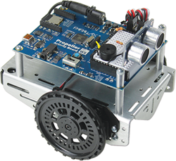
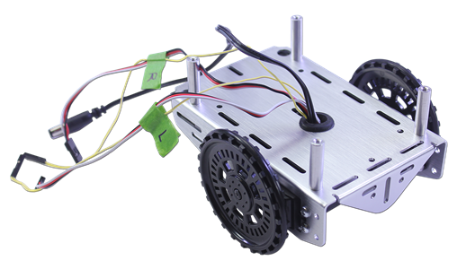
This compact, zippy robot matches a multi-core Propeller microcontroller brain with great hardware:
This tutorial is about building the ActivityBot robot and programming its 8-core Propeller microcontroller brain using the text-based C language. By following these pages step by step, you will learn to:
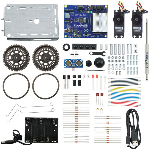
One of these ActivityBot Robot Kit options from Parallax Inc:
To work with the ActivityBot, you will need the SimpleIDE programming software set up. Learning a little about the Propeller microcontroller and practicing some programming before diving into robotics is also a good idea. Complete these short tutorials before you start:
Once you've mastered the basics, you can mod your 'bot with your newfound skills.
...we will help you! Email support@parallax.com [8] .
If your Propeller ActivityBot belongs to a school, it may have been put together already.
Replacement Parts: Most of the pieces in the kit are available for purchase individually online from www.parallax.com [10]. Or, email sales@parallax.com or call 888-512-1024.
This tutorial supports the original ActivityBot Robot Kit (#32500) and the ActivityBot 360° Robot Kit (#32600). What's the difference?
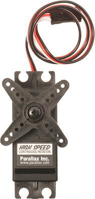
This kit has HIgh Speed Continous Rotation Servos + External Encoders. The servo has a white-red-black 3-wire cable.
Look for instructions mentioning "external encoders."

This kit as Parallax Feedback 360° High Speed Servos. This servo has a white-red-black 3-wire cable, and a separate yellow wire for sending feedback signals. It does not use external encoders, as these servos have encoder sensors built right inside the case.
Look for instructions mentioning "Feedback 360° servos."

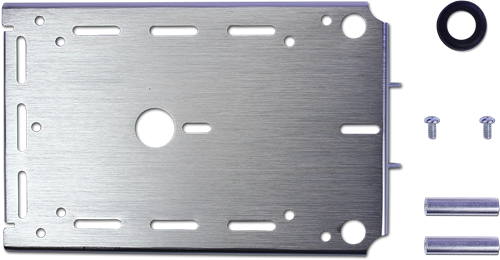
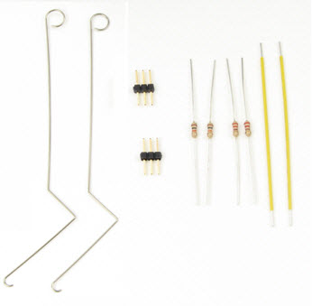
You will use these pieces during the hardware assembly.
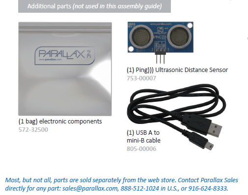
These pieces won't be needed for the hardware assembly, so you can set them aside and save them for later activities.
Have Feedback 360° Servos? If yes, skip this step.
Go to Step 2 - Prepare the Tires [11].
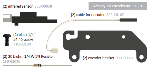
These parts are bagged together as the ActivityBot Encoder Kit. Save the resistors, you will need them later for Electrical Connections.
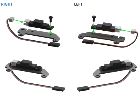
Parts needed for this step:
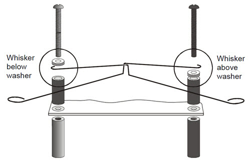
Asemble the right and left encoders to be mirror images of each other.
For all ActivityBot robot kits.
Parts needed for this step:
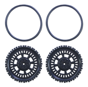
For All ActivityBot Robots
Parts for this step:
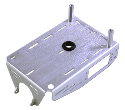
Prepared chassis:
For all ActivityBot robots, whether you have HIgh Speed Servos with X-shaped horns (#900-00025) or Feedback 360° servos with O-shaped horns (#900-00360).
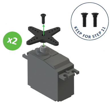
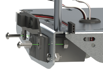
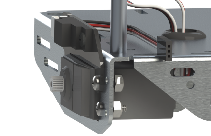
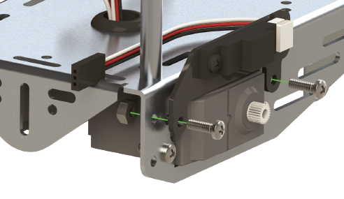
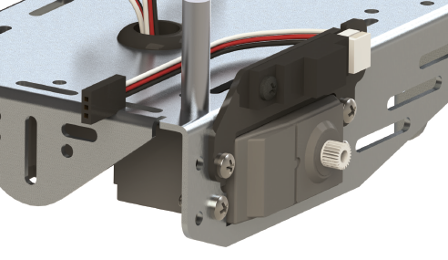
For all ActivityBot robots, but read carefully. Directions are slighty different for robots with external encoders.
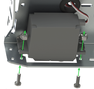
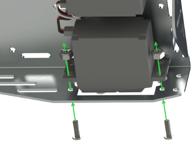
Parts for this step:
Lock-nuts have white Nylon inserts that make a tight grip on screws so they don't loosen easily with vibration. But, they take a little more force to install.
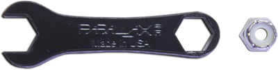
As you work, press the closed end of the little black wrench over each lock-nut to hold it in place while attaching the screws.
Parts needed to complete:
For all ActivityBot robots, but read carefully. Directions are slighty different for robots with external encoders.
Parts for this step:

Parts needed to complete:
Have Feedback 360° Servos? If yes, skip this step.
Go to Step 9 - Mount the Battery Pack [14].
Parts needed for this step:
Have Feedback 360° Servos? If yes, skip this step.
Go to Step 9 - Mount the Battery Pack [14].
Parts needed for this step:
For All ActivityBot Robots.
Parts for this step:
For all ActivityBot robots.
Parts for this step:
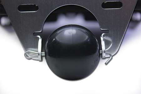
CAUTION - the ends of the cotter pin may be sharp! If you have needle-nose pliers, you can bend the cotter pin ends into a circle to tuck away the points. But be aware that this makes the cotter pin more difficult to remove in the future if you ever want to do that.
This step is for all ActivityBot robots.
Parts needed for this step:
When you are finished, you can turn your robot right-side up!
For all ActivityBot robot kits.
Parts for this step:
For this construction step, you will need:
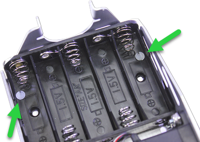
Make sure to use (5) 1.5 V AA batteries!
The ActivityBot's High Speed Continuous Rotation Servos or Feedback 360° servos need 6 to 8 volts. Its 5 cell holder is designed for five alkaline cells because 5 x 1.5 V = 7.5 V. It's true that new and unused 1.5 V alkaline batteries can add up to 8.2 V, but exceeding by only 0.2 V will not harm the servos in any way.
The output of an alternate DC voltage supply should be measured and to make sure it has the correct supply range before using it to avoid potentially damaging the servos.
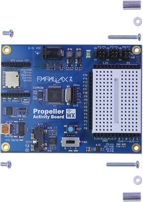
Each pair of 3-pin servo ports along the top of the Propeller Activity Board (original or WX version) has a jumper on power-select pins to its immediate left.
Important! Make sure there is no USB cable or battery pack cable plugged into the board - moving jumpers with power connected could damage your board.
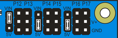
Missing a Voltage Selection Jumper? Replacements are available - contact our sales department [15] to order part #452-00043; there are three per board.
The servos and the external encoders have 3-wire cables: white = signal, red = power, black = ground. When plugging these cables into servo headers, be sure to align white wires with the I/O pin labels along the top of the board, and the black wires along the row labeled GND.
The Feedback 360° servo also has a single yellow encoder feedback signal wire, which plugs onto a separate servo header's I/O pin - closest to the top edge of the board.
With external encoders (left/top); with Feedback 360° servos (right/bottom)
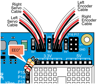
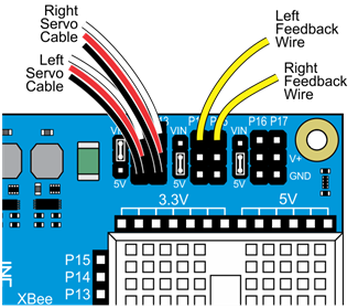
*P14/P15 resistors (shown on left) are only needed for ActivityBot kits using External Encoders (#32500).
It's time to program your ActivityBot! If you've done the prerequisite tutorials listed on the first page of this "book" you already have the SimpleIDE software installed on your computer, and some experience with programming your Propeller Activity Board. If not, it's time to get that done!
The software you will use is called SimpleIDE. It is available for Windows and Mac (and even Linux or the Raspberry Pi if you are willing to compile it). It's an open-source C programming environment for the multi-core Propeller microcontroller. It is important to always use the most recent version of the software, as well as the most recent Learn folder which may be updated separately.
 [16]
[16]
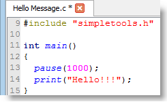
Now it's time to try a little Propeller C programming. This will help you get familiar with the SimpleIDE software and the Propeller C language and Simple Libraries.
 [17]
[17]
Last chance, make sure you have the latest Propeller C Learn folder, with libraries and example code for both the original ActivityBot and the ActivityBot 360°.
Get the latest Propeller C Learn Folder [18]
When you want to try an example program, be sure to look for the file in the right folder for your particular robot:
For ActivityBots with external encoders: ....Documents\SimpleIDE\Learn\Examples\Robots\ActivityBot
-OR-
For ActivityBots with Feedback 360° servos ....Documents\SimpleIDE\Learn\Examples\Robots\ActivityBot 360
It's tempting to dive right into robot navigation. We understand! But, as with any vehicle, it's wise to get familiar with the controls before attempting to drive.
In this section you will:
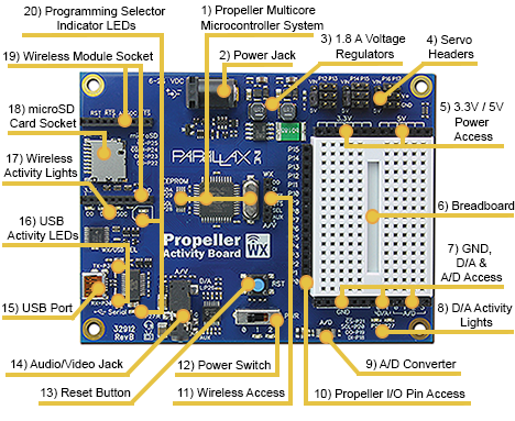
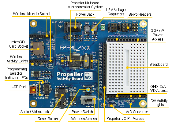
Take a quick tour of the Propeller Activity Board (original or WX version) to get acquainted (or re-acquainted) with its feautres. You've already connected cables to the servo ports and have plugged the battery pack into the power jack. You've been programming it a bit already, so you have been using the USB port.
32912 Product Guide [19]
32912 Product Guide [19]
32910 Product Guide [20]
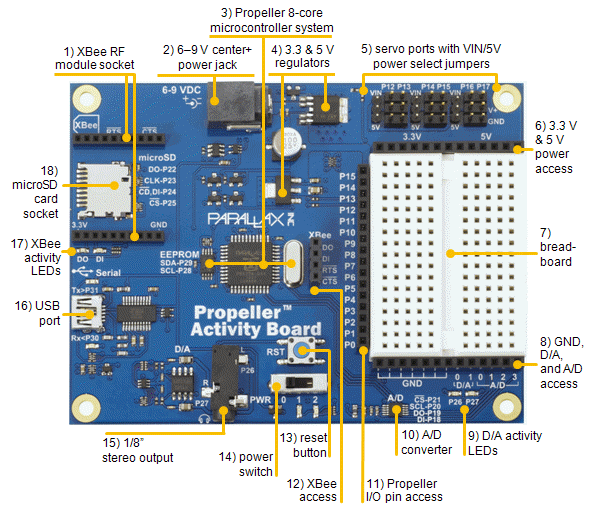
Next, let's take a closer look at two features in particular: the power switch and the breadboard. These features are found on both versions of the Activity Board.
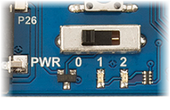
All versions of the Propeller Activity Board have a 3-position power switch:
The breadboard lets you build your own circuits with common electronic components. It's a great way to learn about electricity, and to experiment with making your own inventions. Building experimental circuits to design your own projects is called prototyping, and it is a real-world engineering skill.
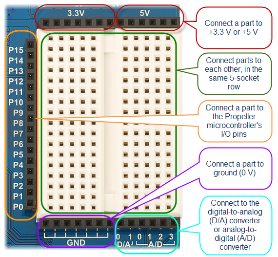
The Activity Board's breadboard (original or WX version) is surrounded on three sides by black sockets. These make it convenient to connect circuits on the breadboard to power, ground, and the Propeller I/O pins. There are also sockets to connect to a digital-to-analog converter and an analog-to-digital converter.
Welcome back! Did you watch the video? If you did, you now know why it's called a "breadboard." History can be pretty interesting!
Next, let's test-drive two built-in light circuits on your Activity Board.
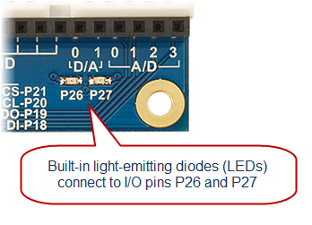
Your Activity Board (original and WX version) has two built-in lights, near the bottom-right corner of the board. These tiny light-emitting diodes (LEDs) are already electrically connected to I/O pins P26 and P27. These LEDs are helpful when developing applications that use sensors. The idea is to write your program so that if a sensor is activated, an LED lights up to give you, the roboticist, a quick visual cue that the sensor is actually detecting something.
The Simple Circuits tutorial has an example program for blinking these LEDs.
Welcome back!
Even though the Propeller chip can play WAV files and synthesize speech, sometimes a simple beep is all the noise you need to get the job done.
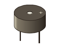
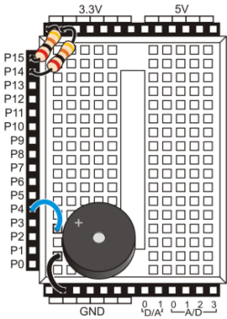
The first breadboard circuit we'll build for the ActivityBot is a simple piezo speaker.
It is very easy to make this speaker beep with a single line of code:
freqout(4, 1000, 3000); // pin, duration, frequency
You can optionally add this line code at the beginning of your ActivityBot example programs. Then, If your robot's batteries run low, the Propeller microcontroller will reset and restart the program—the beep will let you know if this has happened. We include it because it can be very helpful when experimenting with navigation programs, and trying to figure out why your robot is behaving in an unexpected manner.
Welcome back!
Well done! Now you are ready to go on to robot navigation.
This section shows you how to make your ActivityBot move. It covers:
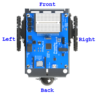
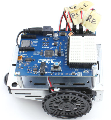
From here forward, we will be talking about the robot's right and left sides, and its front and back. These terms are from the perspective of a tiny person sitting on the white breadboard, with a hand on each post and feet dangling past the edge of the board.

Now you are ready to roll!
Only for FEEDBACK 360° SERVOS
If you are using external encoders, go to External Encoder Test [26] instead.
It's time to test your Feedback 360° servos' encoder signal connections, to make sure they are proper working order. If all is well, the example program below will cause the built-in LED on the Activity Board to blink on and off when you gently turn a wheel by hand.
/*
 Test Feedback Connections.c
*/


#include "simpletools.h"                     // Library - simpletools
#include "abdrive360.h"                      // Library - abdrive360

int left;                                    // Current/previous angles
int right;
int leftPrev;
int rightPrev;

int main()                                   // Main function
{
 drive_getTicks(&left, &right);              // Get current encoder ticks
 leftPrev = left;                            // Set previous values
 rightPrev = right;

 while (1)                                   // Main loop
 {
   drive_getTicks(&left, &right);            // Get current encoder ticks
   if (left != leftPrev)                     // If left different from previous
   {
     toggle(26);                             // Toggle P26 LED light
   }

   if (right != rightPrev)                   // If right different from previous
   {
     toggle(27);                             // Toggle P27 LED light
   }

   leftPrev = left;                          // Save previous values
   rightPrev = right;
 }
}
Here are some symptoms and causes:
Congratulations! It is time to calibrate your ActivityBot.
Only for FEEDBACK 360° SERVOS!
If you are using external encoders, go to External Encoder Calibration [28] instead.
If your ActivityBot is using Feedback 360° servos, calibration is optional, but it will improve the accuracy of driving maneuvers. This is a one-time calibration that the AB360.h library can use for measuring and correcting distances and speeds, using information from the servo's feedback connection.
The calibration code takes about a minute to collect all of its data. You will need a smooth, and obstacle-free, floor area. While the calibration program is running, the ActivityBot will pivot forward and backward, using only one wheel at a time. It will let you know when its done by turning off its P26 and P27 lights (below the breadboard). The video shows an ActivityBot correctly performing the calibration.
IMPORTANT! USE FRESH BATTERIES FOR THIS STEP!
/*
 ActivityBot 360 Calibrate.c
*/

#include "simpletools.h"
#include "abcalibrate360.h"

int main()
{
 cal_servoPins(12, 13);
 cal_encoderPins(14, 15);

 high(26);
 high(27);
 cal_activityBot();
 low(26);
 low(27);
}
What if it Didn't Work?
If your robot didn't move when you started the calibration program, or it started going backwards first instead of forwards, or if it started and stopped right away or just twitched, double-check your electrical connections. You may have a servo cable or feedback signal wire plugged in wrong.
What if I need to re-start or repeat the calibration?
To re-start the calibration process, just push the reset button any time while the P26 and P27 lights are on.
To repeat the calibration process once it has fully completed, you will need to use BlocklyProp to re-load the program. That is because the program modifies itself at the end so that it cannot run a second time. This keeps your ActivityBot from trying to re-calibrate the next time you turn power on to load a new program.
This example program turns on the P26 and P27 LEDs with high(26) and high(27). It then calls the abcalibrate360 library’s cal_activityBot function, which takes the robot through the sequence of motions you just observed. While performing the maneuvers, the cal_activityBot function gathers data that corresponds to the various drive levels it applies to the servos. It stores this data n EEPROM so that every ActivityBot navigation program can use it to fine-tune the drive level needed for going a given speed. When the cal_activityBot function is done, the program turns off the P26 and P27 lights with low(26) and low(27).
Encoders - An encoder converts information from one format to another. The ActivityBot's encoders convert wheel rotation or position into digital information that the Propeller microcontroller can use.
Encoder Ticks are not insects - Throughout this tutorial, you will see the term "ticks" when used to describe the ActivityBot's wheels turning. In this context, a tick means 1/64th of a wheel revolution. When the wheel makes one complete revolution, it has turned 64 ticks. We use ticks per second to note how fast the wheels are turning. Ticks can also refer to distance traveled, when considering the circumference of the ActivityBot wheel.
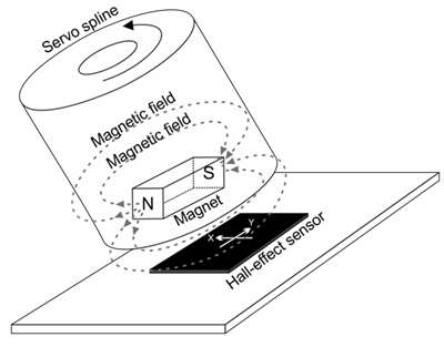
Feedback 360° Servo's Internal Encoders - Each Feedback 360° servo has a tiny magnet inside that is attached to the motor shaft. Also inside the servo's case is a Hall-effect sensor, which can detect changes in the position of the magnetic field as the motor shaft rotates. A tiny processor monitors the Hall-effect sensor and sends position information to the Propeller I/O pin. (For more details, see the Feedback 360° Servo product guide [30].)
There's a block that can check the ActivityBot's calibration data and tell you if there are any mistakes or problems with the ActivityBot's servo, encoder and battery connections. If this test says the calibration was successful, your ActivityBot will be ready to run navigation programs. If not, it will tell you what problem(s) it detected. After finding it and fixing it, make sure to run both the calibration and this test again. Your ActivityBot won't be ready for navigation until it has been calibrated AND passes this test!
/*
  ActivityBot360 Display Calibration Results.c
*/

#include "simpletools.h"
#include "abcalibrate360.h"

int main()
{
  cal_displayResults();
}
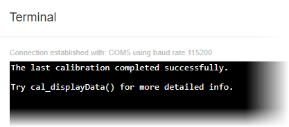
If the terminal output says "...calibration completed successfully...", you can skip to the Your Turn section because the servos, encoders, and power are all connected correctly. So, your ActivityBot is ready to run navigation programs.
Now that your ActivityBot has been calibrated, it is time to run a simple test program to make it drive straight forward. The test code below makes both wheels turn forward at 64 encoder ticks per second for 4 seconds. This should make your ActivityBot roll forward about 1 meter (3 ft.)
/* Forward then Stop.c */
#include "simpletools.h"
#include "abdrive360.h"

int main()
{
  drive_speed(64, 64);
  pause(4000);
  drive_speed(0, 0);
}
Your robot should travel forward for about 1 meter (3 ft.) in a straight line. You may see slight shifts as the robot adjusts its course based on encoder feedback.
First, the lines #include "simpletools.h"and #include "abdrive360.h" make the functions of these two libraries available to the program. ALL of the programs for your ActivityBot 360 will need abdrive360.h specifically. abdrive.h will not work.
Then, inside main, the function drive_speed(64, 64) starts the ActivityBot wheels rotating at a rate of 64 ticks per second. Once you send your ActivityBot a drive_speed instruction, its servos will turn at the specified rate until it receives another drive... instruction, even while other functions are being executed. For example, the function pause(4000) elapses while the ActivityBot drives forward at that rate for 4 seconds. Finally, drive_speed(0, 0) makes the wheels stop turning.
Only for External Encoders!
If you are using Feedback 360° servos, go to Feedback 360° Servo Test [32] instead.
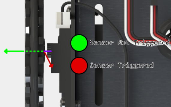
This short test program makes sure each encoder sensor can see the spokes in the wheel right next to it. If the encoder is working properly, a built-in LED on the board will light up each time it detects a spoke, and go off when the hole between the spokes passes by.
/*
  Test Encoder Connections
*/

#include "simpletools.h"

int main()
{
  low(26);
  low(27);
  while(1)
  {
    set_output(26, input(14));
    set_output(27, input(15));
  }
}
Here are some symptoms and causes:
Congratulations! It is time to calibrate your ActivityBot.
Only for External Encoders!
If you are using Feedback 360° servos, go to Feedback 360° Encoder Calibration [27] instead.
Before running any other example programs, your ActivityBot needs to be calibrated. This is a one-time calibration that the abdrive library needs for measuring and correcting disances and speeds, using information from the ActivityBot encoders.
The calibration collects requested speed vs. measured speed data and stores it in a part of the ActivityBoard’s EEPROM memory, where it can retain data even after you turn the power off. That way, the calibration data is available every time you turn the robot back on.
When your program asks for a certain wheel speed, the abdrive library will use the calibration data from EEPROM to start driving the motors at speeds close to what your program asks for. That way, abdrive doesn’t have to make large corrections, just small ones, which improves overall accuracy.
The calibration program takes less than 2 minutes to collect all of its data. You will need a smooth and obstacle-free floor area that’s roughly one meter square. While the calibration program is running, the ActivityBot will go in circles at various speeds, using only one wheel at a time. It will let you know when its done by turning off its P26 and P27 lights (below the breadboard). The above video shows an ActivityBot correctly performing the calibration.
IMPORTANT! USE FRESH BATTERIES FOR THIS STEP!
IMPORTANT! Your ActivityBot Library needs to be installed in the correct location BEFORE attempting to run this, or any other, ActivityBot program.
The ActivityBot library folder should be in ...Documents\SimpleIDE\Learn\Simple Libraries\Robotics. If you install the library folder yourself, unzip the library folder and then make sure to close and then re-open SimpleIDE before continuing on to allow the software to cache the library location.
Return to Software and Programming [24] for the library download and additional instructions, if necessary.
What if it Didn't Work?
If your robot didn't move when you started the calibration program, started going backwards first instead of forwards, started and stopped right away, or just twitched instead of moving, go to the Troubleshooting [36]page for help.
Re-starting the Calibration Program
If you need to re-start the calibration process, you can push the reset button any time while the P26 and P27 lights are on. Once the calibration process is complete, the program image gets modified so that it cannot run a second time. This keeps it from trying to re-calibrate the next time you turn power on to load a new program. If you want to re-run the calibration, you will need to use SimpleIDE to load ActivityBot Calibrate into EEPROM again.
This example program turns on the P26 and P27 LEDs with high(26) and high(27). It then calls the abcalibrate library’s cal_activityBot function, which takes the robot through the sequence of motions you just observed. While performing the maneuvers, the cal_activityBot function builds a list of wheel speeds that correspond to the various drive levels it applies to the servos. It stores those values in EEPROM so that every ActivityBot navigation program can use them to find out what drive level is needed for going a given speed. When the cal_activityBot function is done, the program turns off the P26 and P27 lights with low(26) and low(27).
/*
  ActivityBot Calibrate.c

  Calibrate the ActivityBot's servos and encoders
*/

#include "simpletools.h"
#include "abcalibrate.h"

int main()
{
  cal_servoPins(12, 13);
  cal_encoderPins(14, 15);

  high(26);
  high(27);
  cal_activityBot();
  low(26);
  low(27);
}
Encoder Ticks - Each ActivityBot encoder shines infrared light at the ring of 32 spokes in the wheel next to it. If the light passes between the spokes, the encoder sends the Propeller a high signal. If it bounces off a spoke and reflects back to the encoder’s light sensor, it sends a low signal to the Propeller. Each time the signal changes from high to low, or low to high, the Propeller chip counts it as an encoder tick.
Sensing Direction — The Propeller chip knows what direction the servos turn based on the signal it uses to make the servo move. All it needs from the encoder is to know how fast it’s turning. It does this by counting encoder ticks over a period of time. The libraries keep track of all this for you, so your programs just need to tell the robot robot how far or how fast to go.
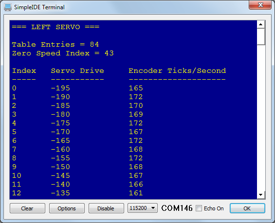
Interpolation — The cal_activityBot function builds a table of data points for motor drive level and the actual speed the wheels turned. Navigation programs will use those data points to figure out how hard to drive a wheel to get a certain speed. If the speed the program asks for is between two data points, the navigation library will figure out the best drive value between two of the known values. For example, if the table has data points for 60 and 80 encoder ticks per second, and your program asks for 70 ticks per second, the navigation library will use a motor drive level that’s half way between the 60 and 80 ticks per second levels. This process is called interpolation and the data set is called a linear interpolation table.
You can check to see if the calibration was successful, and if not, see a message that may help diagnose the problem.
You can use the program below to view it.
/*
ActivityBot Display Calibration Results.c
*/

#include "simpletools.h"
#include "abdrive.h"

int main()

{
 drive_calibrationResults();
}
The Terminal will display a message either confirming that your calibration was successful, or a suggestion for troubleshooting your connections if calibration failed.
The function drive_displayInterpolation will display the actual lists of values that are stored in EEPROM. This interpolation table data can be very helpful for troubleshooting [36] if your robot does not drive as expected after calibration.
Now that your ActivityBot has been calibrated, it is time to run a simple test program to make it drive straight forward. The test code below makes both wheels turn forward at 64 encoder ticks per second for 4 seconds. This should make your ActivityBot roll forward about 1 meter (3 ft.).
/* Forward then Stop.c */
#include "simpletools.h"
#include "abdrive.h"

int main()
{
  drive_speed(64, 64);
  pause(4000);
  drive_speed(0, 0);
}
Your robot should travel forward for about 1 meter (3 ft.) in a straight line. You may see slight shifts as the robot adjusts its course based on encoder feedback.
First, the lines #include "simpletools.h"and #include "abdrive.h" make the functions of these two libraries available to the program. ALL of the programs for your ActivityBot with external encoders will need abdrive.h specifically. abdrive360.h will not work.
Then, inside main, the function drive_speed(64, 64) starts the ActivityBot wheels rotating at a rate of 64 ticks per second. Once you send your ActivityBot a drive_speed instruction, its servos will turn at the specified rate until it receives another drive... instruction, even while other functions are being executed. For example, the function pause(4000) elapses while the ActivityBot drives forward at that rate for 4 seconds. Finally, drive_speed(0, 0) makes the wheels stop turning.
Although it’s possible to go a certain distance by choosing a speed and calculating the time, there is an easier way. Fortunately, the abdrive and abdrive360 libraries have a function that takes care of all that. It’s called drive_goto, and you can use it to tell the ActivityBot how far each wheel should turn in terms of 3.25 mm increments.
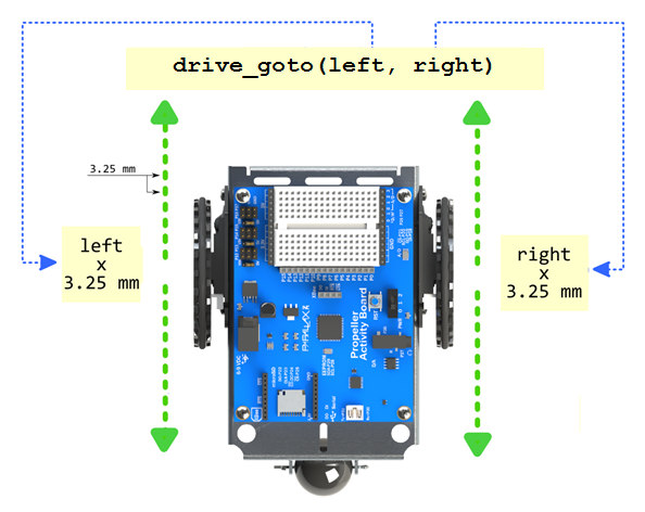
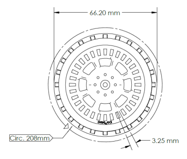
Recall that the term “tick” indicates 1/64th of a wheel rotation. If the wheel turns 64 ticks, it makes one complete revolution. That would make the robot travel the distance of its wheel circumference, which is 208 mm. So, if the wheel turns 1/64th of a turn—that’s a tick’s worth—it will travel 3.25 mm.
If you know how far you want your ActivityBot to roll, just divide the distance by 3.25 mm (or 0.325 cm or 0.00325 m) to find out how many ticks your program needs to tell the ActivityBot to travel.
ticks = distance mm ÷ 3.25 mm/tick
The ActivityBot’s turning radius is typically 105.8 mm.
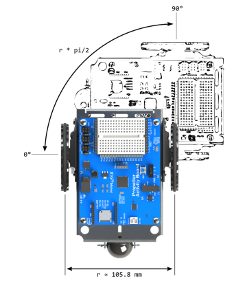
If you hold the right wheel still and make the left wheel turn, it will have to turn 2 × π × r. In this case, the r is the turning radius, so that’s 2 × π × 105.8 mm ≈ 664.76 mm. If you want the ActivityBot to make a ¼ turn, that would be 664.76 mm ÷ 4 ≈ 166.2 mm. How many wheel ticks is that? 166.2 mm ÷ 3.25 mm/tick ≈ 51.14 ticks ≈ 51 ticks.
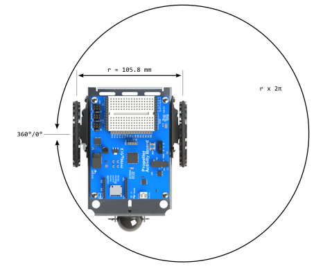
TIP: If you make one wheel go forward 26 ticks, and the other go backwards 25 ticks, that’s still a total of 51 ticks for ¼ of a turn.
This test code makes the ActivityBot go forward 256 ticks, and then turn and face 90-degrees to the right.
The program makes the ActivityBot go forward by 256 ticks (four wheel turns). Then, drive_goto(26, -25) makes the ActivityBot execute a 90-degree right turn.
#include "simpletools.h"
#include "abdrive.h"

int main()
{
  drive_goto(256, 256);
  pause(200);
  drive_goto(26, -25);
}
Overshoots — If the drive_goto function overshoots, it backs up to the correct number of ticks.
Expand the program to make the ActivityBot retrace its path back to where it started, after going forward and turning right. There are two ways you could accomplish this:
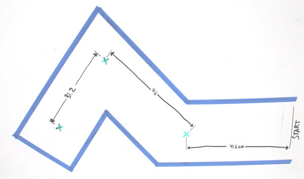
Simple waypoint navigation challenges involve programming your robot to drive a pre-determined course. An example course is shown below. To run this course, you would need to program your ActivityBot for the following manueuvers (this will take a bit of math):
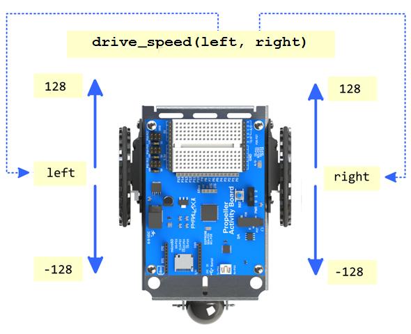
Sometimes your ActivityBot might need to go a certain direction until it runs into an obstacle. Setting the robot to go a certain speed, instead of a certain distance, is helpful for that kind of application.
We can do this with the abdrive library's drive_speed function. It sets each drive servo to a certain speed, in encoder ticks per second. Since there are 64 ticks in a wheel turn, if you set a wheel speed to 64 ticks per second, that’s one full turn per second. Use positive values for forward, and negative values for reverse.
We’ll also try a drive_ramp function that lets the ActivityBot speed up and slow down gradually. This prevents its wheels from losing traction, and helps keep the robot from tipping forward from abrupt stops.
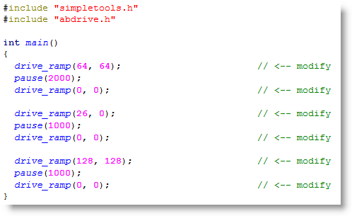
This example sets the robot to go straight ahead at 64 ticks/second until it has gone more than 200 ticks forward. Then it executes a 45-degree right turn with the left wheel turning 32 ticks per second. After that, it continues for another 200+ ticks at 128 ticks per second.
The program sets out by setting both servos to turn at 64 ticks per second with drive_speed(64, 64). Since 64 ticks per second is one full wheel revolution per second, and since a pause(2000) follows it, we know the wheels should both turn at 64 ticks per second for two seconds. In terms of distance, that should be 64 ticks/second x 2 seconds = 128 ticks. Keep in mind that this may not be precise because the robot will have some momentum when it gets to drive_speed(0, 0). Also keep in mind that if you do want a more precise distance traveled, just use the drive_goto function.
#include "simpletools.h"                      // simpletools library
#include "abdrive.h"                          // abdrive library

int main()
{
  drive_speed(64, 64);                       // Forward 64 tps for 2 s
  pause(2000);
  drive_speed(0, 0);

  drive_speed(26, 0);                        // Turn 26 tps for 1 s
  pause(1000);
  drive_speed(0, 0);

  drive_speed(128, 128);                     // Forward 128 tps for 1 s
  pause(1000);
  drive_speed(0, 0);
}
Next, drive_speed(26, 0) makes the left wheel turn at about 26 ticks per second, while the right wheel stays still. Since it’s going for 1 second, the left wheel should turn about 26 ticks for a 45-degree turn. drive_speed(0, 0) stops it after the 1 second. The last maneuver should go about the same distance as the first maneuver, but it’s going twice as fast (128 ticks per second instead of 64) for half the time (1 second instead of 2 seconds).
Velocity is speed, but it can be either positive (like forward) or negative (like backward). Speed itself is just velocity without the sign. So, if you are going backwards at a speed of 5 km/hr, you could also call that a velocity of -5 km/hr.
Here is an equation you can use to calculate distance (s) given velocity (v) and time (t).
s = v × t
Example: A car goes 40 km/hr, how many km does it travel in 0.25 hours? Answer: s = v × t = 40 km/hr × 0.25 hr = 10 km.
Applied to the ActivityBot, if a wheel goes 64 ticks per second for 2 seconds, that’s v = 64 ticks per second and t = 2 seconds. So:
s = 64 ticks/second × 2 seconds = 128 ticks.
For a distance in centimeters, remember that a tick is 0.325 cm, so the wheel travels:
s = 128 ticks × 0.325 cm/tick = 41.6 cm.
If you divide both sides of s = v × t by v, you get:
t = s ÷ v
…and that’s really useful for picking a time to go a certain direction if you know the speed and distance you want the ActivityBot to go.
Example: The ActivityBot needs to go 192 ticks forward at a rate of 64 ticks per second.
If you noticed some sudden starts and stops in the previous example programs, these can be cushioned with drive_ramp. This function gradually speeds up or slows down the wheels.
You can also use drive_speed to make the ActivityBot travel in curves.
#include "simpletools.h"
#include "abdrive.h"

int main()
{
  drive_speed(80, 60);
  pause(2000);
  drive_speed(0, 0);
}
If your program ever needs to know how many ticks each wheel has traveled, you can use the drive_getTicks function. Here is an example that records the number of ticks traveled before and after the Try This program that curved to the right. Use Run with Terminal, and leave your robot plugged in. (Try setting the robot on a stand or hold it above the desk so that it doesn't go to far while attached to the USB cable.)
Your challenge is to add two more maneuvers and display the distance traveled for each maneuver.
Hint: You can calculate distance for each maneuver by using something like: distanceLeft = distLeft[1] - distLeft[0];
#include "simpletools.h"
#include "abdrive.h"

int distLeft[4], distRight[4];

int main()
{
  drive_getTicks(&distLeft[0], &distRight[0]);

  print("distLeft[0] = %d, distRight[0] = %d\n", distLeft[0], distRight[0]);

  drive_speed(80, 60);
  pause(2000);
  drive_speed(0, 0);

  drive_getTicks(&distLeft[1], &distRight[1]);

  print("distLeft[1] = %d, distRight[1] = %d\n", distLeft[1], distRight[1]);
}
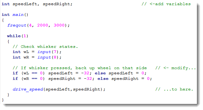
Whisker sensors allow your robot to detect obstacles by bumping into them. When the robot's whisker bumps into an object, it makes an electrical connection between the whisker and a circuit on the breadboard. In this lesson, you will program your robot’s Propeller microcontroller to detect those contacts and make the robot avoid obstacles.
The next picture shows whisker wiring. Along with the whisker circuits, it has the same piezospeaker we've been using.
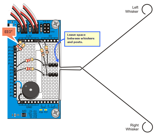
*P14/P15 resistors are only needed for ActivityBot kits using External Encoders (#32500).
It’s important to test the whisker contacts before programming your robot to navigate with them. That way, you can be sure the whiskers are sending the right messages. Otherwise, they might be telling the Propeller that they detect something even though they didn't, or vice-versa.
If either of the numbers are zeros, or if either of them flicker between 1 and 0, there's probably a circuit error.
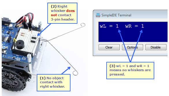
Next, let's check to make sure the Propeller chip detects when the right whisker is pressed or makes contact with an obstacle.
The main function starts with our now-familiar reset indicator code: freqout(4, 2000, 3000) makes the speaker connected to P4 beep for 2 seconds at a frequency of 3 kHz.
After that, the program enters a while(1) loop that repeats endlessly. Inside that loop, int wL = input(7) copies the value that input(7) returns into an int variable named wL (short for whisker-Left). The input(7) call might return a 1, which would indicate that the left whisker is not pressed. Or, it might return a 0, indicating that it is pressed. In either case, that 1 or 0 value gets copied to the wL variable. The int wR = input(8) statement works roughly the same way, except that it stores the 1 or 0 value for the right whisker circuit, which is connected to P8, into a variable named wR (short for whisker-Right).
/*
  Test Whiskers with Terminal.c

  Display whisker states in terminal.  1 = not pressed, 0 = pressed.

*/

#include "simpletools.h"                      // Include simpletools header

int main()                                    // main function
{
  freqout(4, 2000, 3000);                     // Speaker tone: P4, 2 s, 3 kHz
  while(1)                                    // Endless loop
  {
    int wL = input(7);                        // Left whisker -> wL variable
    int wR = input(8);                        // Right whisker -> wR variable
    print("%c", HOME);                        // Terminal cursor home (top-left)
    print("wL = %d  wR = %d", wL, wR);        // Display whisker variables
    pause(50);                                // Pause 50 ms before repeat
  }
}
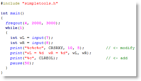
After storing the whisker states in the wL and wR variables, print("%c", HOME) sends the cursor to the home position. The %c format string tells the print function to send the value of a char variable. HOME is the number 1, and when print sends that value to the SimpleIDE Terminal, the terminal moves its cursor to the top-left “home” position. After that, print("wL = %d wR = %d", wL, wR) displays the values of the wL and wR variables. This time, the %d format string made the print function display values as decimal characters, in this case, either 1 or 0 for the whisker states.
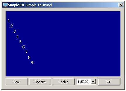
The simpletools library has 16 control characters you can use to do things like clear the screen and position the cursor.
| Name | Value | Description |
| HOME | 1 | Send cursor to the top-left (home) position |
| CRSRXY | 2 | Position the cursor. Follow with x and y values. Example places cursor 10 spaces in and 5 lines down: print("%c%c%c ", CRSRXY, 10, 5); |
| CRSRLF | 3 | Move cursor one space to the left |
| CRSRRT | 4 | Move cursor one space to the right |
| CRSRUP | 5 | Move cursor one line up |
| CRSRDN | 6 | Move cursor one line down |
| BEEP | 7 | Make the host computer beep |
| BKSP | 8 | Backspace |
| TAB | 9 | Tab |
| NL | 10 | Send cursor to next line |
| CLREOL | 11 | Clear text to right of cursor |
| CLRDN | 12 | Clear text below cursor |
| CR | 13 | Carriage return |
| CRSRX | 14 | Position cursor x spaces to the right |
| CRSRY | 15 | Position cursor y lines down |
| CLS | 16 | Clear the display |
Here is a program you can try that positions the cursor at 10 spaces over and 5 lines down before printing the whisker states.
Let's take a look at the right whisker and see what happens when it is not pressed, and then pressed.
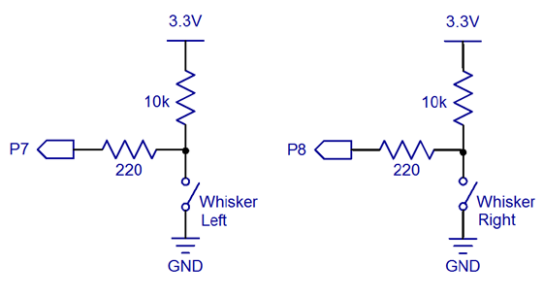
When it's not pressed the whisker does not touch the 3-pin header on the breadboard, so there is no electrical contact between the two. Because of that, the 10 kΩ resistor that’s connected to the 3.3 V socket above the breadboard applies 3.3 V to the breadboard row with the 3-pin header post. The 220 Ω resistor that connects that row to P8 applies the 3.3 V to P8.
The whisker is like a normally open switch. In the schematic, P8 detects 3.3 V through the 220 Ω and 10 kΩ resistors. Whenever a circuit applies 3.3 V (or anything over 1.65 V) to P8, input(8) returns 1. That's why wR = input(8) copied the value of 1 to the wR variable (and you saw it displayed in the SimpleIDE Terminal).
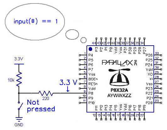
Why 3.3 V at P8? In case you’re wondering why the voltage at P8 is the same as the voltage above the 10 kΩ resistor, here’s what’s going on:
First of all, the schematic shows an open switch with the “Not pressed” label. That open switch is the whisker, which is not in contact with the 3-pin header, and it keeps ground (GND = 0 V) out of the circuit. So, all we have is 3.3 V on one end of a pair of resistors, and P8 on the other end. Since P8 is set to input, it looks invisible to the circuit. As far as the circuit’s concerned, the right side of that 220 Ω resistor might as well be disconnected from everything and sticking up in the air. When only one voltage is applied to a resistor, or even a chain of resistors, that same voltage will appear at the other end as well. So, P8 as an input is invisible to the circuit, but it can detect the voltage the circuit applies to it. In this case, that voltage is 3.3 V, which causes the Propeller to store 1 in its P8 input register, and so input(8) returns the value 1.
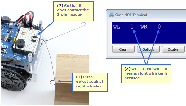
When the right whisker is pressed because the robot has bumped into an obstacle, then the right whisker makes contact with the front post on the 3-pin header. The whisker is electrically connected to that plated hole on the corner of the board, which eventually makes its way to the battery's negative terminal. That negative terminal is commonly called ground, and has a value of 0 V. Since the whisker touches that 3-pin header post, it connects that row to ground, so P8 sees 0 V through the 220 Ω resistor.
Take a look at this schematic. It shows how the whisker connects that node where the 10 kΩ and 220 Ω resistors meet to ground (0 V). ...and that's what P8 detects. As a result, a call to input(8) returns zero. That zero value gets copied to wR with wR = input(8), and that’s what gets displayed by the Parallax Terminal Window when the whisker is pressed.
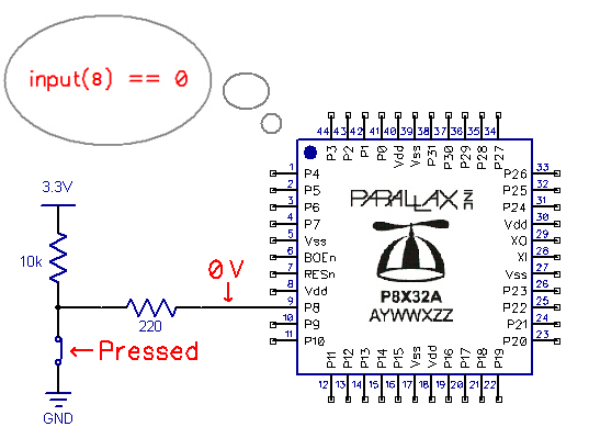
Why 0 V at P8? Now that the whisker is pressed, the schematic above shows 0 V applied to P8. That’s because pushing the whisker up against the post connects GND (0 V) to the node where the 10 kΩ and 220 Ω resistors meet. Now, instead of 3.3 V, the circuit applies 0 V to P8. Reason being, 0 V is being applied to the left side of the 220 Ω resistor, and the circuit still thinks the right side of that resistor is floating in the air. So, the rule for a high impedance input still applies, and the voltage that’s on the right side of the 220 Ω resistor will be the same as the voltage applied to its left side.
Now that there’s 3.3 V on one end of the the 10 kΩ resistor and 0 V on the other end, it applies electrical pressure that causes current to flow through that resistor. You can use the Ohm’s Law equation of V = I x R to figure it out. This equation says the voltage (V) difference at two ends of a resistor is equal to the current (I) pasing through it multiplied by the resistor’s resistance (R). With a little algebra, we have I = V ÷ R = 3.3 V ÷ 10,000 Ω ≈ 0.00033 A. That’s 0.00033 A, or in terms of milliamps, 0.33 mA, a very small amount of current, especially compared about 140 mA, which is what the servos need to make the Propeller ActivityBot move.
The 10 kΩ resistor is called a pull-up resistor. It pulls the voltage at P8 up to 3.3 V when the whisker is not pressed. It's important to have either a pull-up or pull-down resistors in switch circuits. A pull-up or pull-down resistor applies a voltage that’s opposite of the voltage the I/O pin will detect when the switch/button contact is made. Without it, the I/O pin will allow nearby electric fields to affect whether it reports 1 or 0 to the input function. For example, without that pull-up/pull-down resistor, simply putting your hand near the 220 Ω resistor might change the value the input function reports.
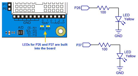
As you built the whisker circuits on your board, you connected two Propeller I/O pins to LEDs that are built into the circuit board. That means you can program the Propeller to send high/low signals to these I/O pins, which will turn the connected LEDs on/off.
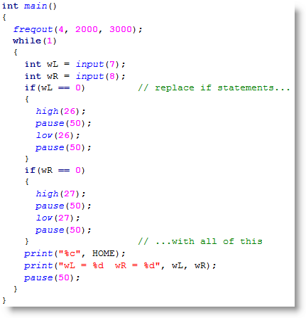
Test Whiskers with LEDs.c is just the previous program with two if...else statements added. First, if(wL == 0) high(26); else low(26) does one of two things. If wL stores 0, it means the left whisker is pressed, so high(26) turns on the P26 LED. If wL stores 1, it means the whisker is not pressed. In that case, low(26) turns the LED off. The second line that was added is if(wR == 0) high(27); else low(27). It does the same job, except that it turns the P27 LED on/off depending on whether wR stores a 1 or 0.
/*
  Test Whiskers with LEDs.c

  Display whisker states in terminal.  1 = not pressed, 0 = pressed.

*/

#include "simpletools.h"                      // Include simpletools header

int main()                                    // main function
{
  freqout(4, 2000, 3000);                     // Speaker tone: P4, 2 s, 3 kHz
  while(1)                                    // Endless loop
  {
    int wL = input(7);                        // Left whisker -> wL variable
    int wR = input(8);                        // Right whisker -> wR variable
    if(wL == 0) high(26); else low(26);       // Light for left whisker
    if(wR == 0) high(27); else low(27);       // Light for right whisker
    print("%c", HOME);                        // Terminal cursor home (top-left)
    print("wL = %d  wR = %d", wL, wR);        // Display whisker variables
    pause(50);                                // Pause 50 ms before repeat
  }
}
You can modify the program to make the lights blink when the whiskers are pressed like this:
Your challenge is to modify the Your Turn code to make it blink 10 times each time you press a whisker.
Hint: Review Counting Loops [39]. You can nest a for loop inside an if statement.
Now let's try a program that makes the robot back up while you push and hold a whisker up against its breadboard post.
Before starting the while(1) loop, the program has its usual freqout call to make the speaker beep.
Inside the main function’s while(1) loop, the first two lines should look familiar: they test the whisker input states and assign the result to wL and wR.
Next, we have if((wL == 0) || (wR == 0)) followed by a code block. It means, “if wL stores 0 OR wR stores 0, do what is inside the code block.” So, if either variable does store 0, then, drive_speed(-64, -64) runs the robot's servos backwards for 20 ms.
If neither whisker variable stores a 0, the program execution skips that if... code block and moves on to the else code block below. There, it stops both servos with drive_speed(0, 0).
/*
  Whiskers Push Bot.c
  Push the whiskers to make the Propeller ActivityBot back up.
*/

#include "simpletools.h"                      // Include simpletools header
#include "abdrive360.h"                          // Include abdrive header

int main()                                    // main function
{
  freqout(4, 2000, 3000);                     // Speaker tone: 2 s, 3 kHz

  while(1)
  {
    // Check whisker states.
    int wL = input(7);                        // Left whisker -> wL variable
    int wR = input(8);                        // Right whisker -> wR variable

    // If whisker pressed, back up
    if((wL == 0) || (wR == 0))                // Either whisker detects
    {
      drive_speed(-64, -64);                  // Back up
    }
    else                                      // Neither whisker detects
    {
      drive_speed(0, 0);                      // Stay still
    }
  }
}
Here is a modified loop for your main function. It replaces the if...else statements with code that allow you to push one whisker at a time to make it turn away to one side or the other, or both whiskers to make it move straight backwards.
Now that you've learned how to make the robot react to its whiskers, let's expand on that and make it roam with whiskers.
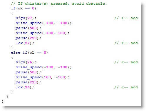
To roam, the robot needs to go forward until it bumps into something. When that happens, it needs to back up, turn away from the obstacle, and then go forward again. While the robot is going forward, it should repeatedly check its whiskers with minimal delays between whisker checks. That way, it can know right away when it has encountered an obstacle.
Look at the two lines inside the while(1) loop. drive_speed(100, 100) makes the robot go full speed forward for a 50th of a second.
The next two lines copy the whisker states to the wL and wR variables.
Next, two else if statements check in turn to see if just one whisker or the other is pressed. If just one whisker is pressed, the robot will back up straight for one second, and then turn away from the pressed-whisker side for 0.6 seconds. If both whiskers are pressed, the robot will back up and then decide to turn either left or right.
If no whiskers are pressed, none of the conditions in the entire set of if...else if...else if statements will be true, so none of those code blocks will get executed. The result is that the robot just keeps rolling forward and checking its whiskers every 20 ms.
/*
  Roaming with Whiskers.c
  Go forward until object detected by whisker(s).  Then, back up, turn
  and go a new direction.
*/

#include "simpletools.h"                        // Include simpletools library
#include "abdrive360.h"                         // Include abdrive library

int main()                                      // main function
{
  freqout(4, 2000, 3000);                       // Speaker tone: 2 s, 3 kHz

  while(1)                                      // main loop
  {
    // Go forward for 1/50th of a second.
    drive_speed(100, 100);                      // Go forward

    // Check whisker states.
    int wL = input(7);                          // Left whisker -> wL variable
    int wR = input(8);                          // Right whisker -> wR variable

    // If whisker(s) pressed, avoid obstacle.
    if(wR == 0)                                 // Just right whisker
    {
      drive_speed(-100, -100);                  // Back up 0.5 seconds
      pause(500);
      drive_speed(-100, 100);                   // Turn left 0.22 seconds
      pause(220);
    }
    else if(wL == 0)                            // Just left whisker
    {
      drive_speed(-100, -100);                  // Back up 0.5 seconds
      pause(500);
      drive_speed(100, -100);                   // Turn right 0.22 seconds
      pause(220);
    }
  }
}
It’s nice to have the lights turn on to indicate which whisker the robot is avoiding. Here is a modified code block for the if... statement that makes the LEDs light up for the whiskers that have been pressed.
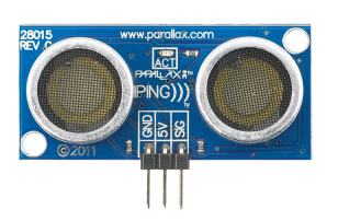
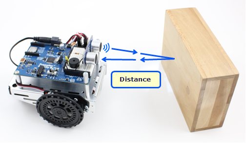
The Ping))) Ultrasonic Distance Sensor lets your ActivityBot detect obstacles and measure the distance to them. Even though the PING))) sensor looks a bit like eyes, it is more like a mouth and an ear.
Much like a bat, the PING))) sensor emits an ultrasonic chirp when triggered, then listens for the chirp's echo and signals its return. The Propeller microcontroller can mark the time between triggering the PING))) sensor and getting a return signal. This echo return time can then be used to calculate the distance to an object.
This ability makes different ActivityBot navigation strategies possible, such as avoiding obstacles while roaming, or maintaining a set distance to an object that is moving.
In this activity, you will build the PING))) sensor circuit and use it to measure distances of a variety of objects to get familiar with what it does and does not detect. The PING))) sensor just needs power, ground, and one signal connection for the Propeller to get distance measurements.
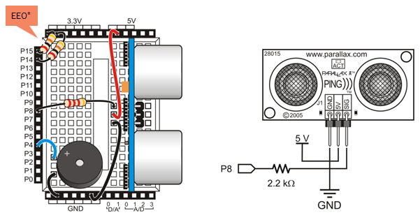
*P14/P15 resistors are only needed for ActivityBot kits using External Encoders (#32500).
Ping))) Sensor and Servo Ports: When you are ready to design your own projects, you might want to mount the Ping))) sensor somewhere else on the robot. To make this easier, you can set the P16–P17 servo port power jumper to 5V, and then connect the sensor to one of those ports with a 3-pin extension cable. Each servo port includes a 3.9 k-ohm resistor in series with its Propeller I/O pin, so you would not need to include the 2.2 k-ohm resistor that is needed for the breadboard circuit.
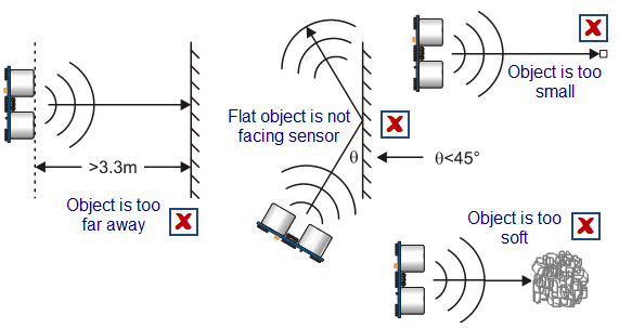
The PING))) sensor's echo-location works on objects that can effectively reflect sound back at the sensor, from up to 3.3 meters away. Small objects don't reflect back enough sound. Hard-surfaced cylinders, ball-shaped obstacles, and walls if faced directly, work well. Walls that are approached at glancing angle will simply reflect the sound further away instead of back at the PING))) sensor. Soft items such as curtains and stuffed animals tend to muffle the sound and not bounce the echo.
For obstacles that do reflect sound back, the PING))) sensor and ping library provide centimeter distance measurements in the 3 cm to 3 m range. Air temperature can affect the accuracy of these distance measurements. Check out this reference article [40] about the speed of sound vs. air temperature to learn more about why this happens.
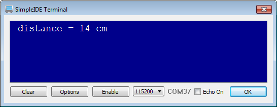
The test program will display the PING))) distance measurements in the SimpleIDE terminal. You can use it to test how well the PING))) sensor can detect various objects, and walls at various angles, to get familiar with what your ActivityBot can and cannot do with this sensor.
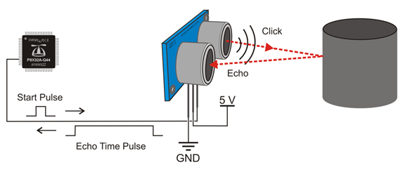
The PING))) sensor requires a brief high/low signal called a start pulse from the Propeller chip to start the measurement. The sensor then makes its ultrasonic click and sets its SIG pin high. When the echo comes back, it sets its SIG pin low. The Propeller chip then can measure the duration of the PING))) sensor SIG pin's high signal, which corresponds to the echo return time.
The ping library takes care of the math for converting the echo return time measurement to distance in centimeters. All your code has to do is request the distance with the ping_cm function, and pass to it the number of the Propeller I/O pin connected to the sensor. In the test code, the function's return value gets stored in a variable named distance. Then, it gets displayed in the SimpleIDE terminal with print(“%c distance = %d cm %c”, HOME, distance, CLREOL). This particular print statment puts the cursor in the top-left home position with HOME, displays the distance, and then CLREOL clears any characters to the end of the line. CLREOL is useful if the previous measurement has more digits than the current measurement. (If the program skipped that step, it would display cmm instead of cm after the measurement if it happens to be one less digit than the previous measurement. Try it if you want.)
/*
  Test Ping.c

  Test the PING))) sensor before using it to navigate with the ActivityBot.

*/

#include "simpletools.h"                      // Include simpletools header
#include "ping.h"                             // Include ping header

int distance;                                 // Declare distance variable

int main()                                    // main function
{
  while(1)                                    // Repeat indefinitely
  {
    distance = ping_cm(8);                    // Get cm distance from Ping)))

    print("%c distance = %d%c cm",            // Display distance
           HOME, distance, CLREOL);

    pause(200);                               // Wait 1/5 second
  }
}
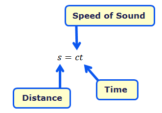
The ping library measures the echo pulse in terms of microseconds and then uses the fact that sound travels at 0.03448 cm/µs at room temperature. That’s 3.448 hundredths of a centimeter per millionth of a second at a temperature of (22.2 ºC). Just as a car travels distance = speed x time, so does sound, with an equation of s = ct, where s is the distance, c is the speed of sound and t is the time.
To calculate the distance of an echo, you have to remember that the time measurement is for twice the distance (there and back), so the equation would be:

Divide both sides by 2, and you’ve got an equation for distance from a time measurement.

Since 0.03448/2 ≈ 1/58, the equation for cm distance from microsecond echo time becomes:

Check out our Reference page on the "Speed of Sound in Air v. Temperature [41]" to learn how air temperature affects ultrasonic sensor readings.
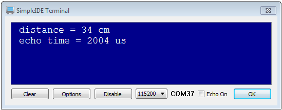
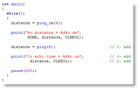
You can display the raw microsecond time measurements with a call to the ping function.
Now that you can measure centimeter distances with the PING))) sensor, and know which kinds of objects it can sense, let’s put it to work in navigation.
All your code has to do is make the robot go forward until it receives a distance measurement from the PING))) sensor that’s less than some pre-defined value, say 20 cm. Then, slow down to a stop. After that, turn in place until the measured distance is more than 20 cm. At that point, it’ll be safe to go forward again. To make the ActivityBot's navigation a little more interesting, your code can also use random numbers to decide which direction to turn.
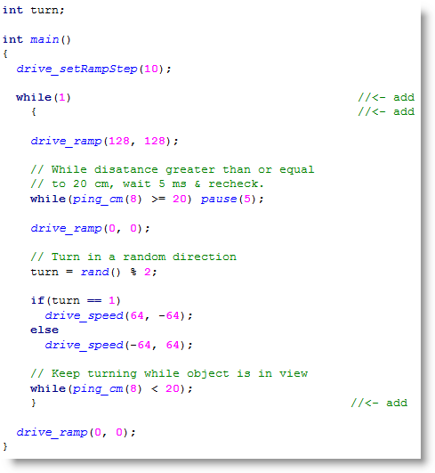
Before actually roaming, it’s important to test a smaller program to make sure your ActivityBot will stop in front of an obstacle, and turn away from it. This example program makes the ActivityBot go forward while the PING))) measured distance is greater than 20 cm. If the distance measures less than or equal to 20 cm, the robot ramps down to a stop. Then, it turns in place until it measures more than 20 cm, which means the robot turned until the object is no longer visible.
This program doesn’t use distance = ping_cm(8). Instead, it just takes the value ping_cm(8) returns, and uses it in decisions. So, it doesn’t need to declare a distance variable; however, it does still need a variable for storing a random number to decide which way to turn. So before the main function, there's a declaration for a variable named turn.
The program starts with drive_setRampStep(10), which sets the number of ticks per second that the speed is allowed to change for every 50th of a second. Since the function call passes 10, it means the speed can only change by 10 ticks per second, every 50th of a second. Next, drive_ramp(128, 128) ramps up to full speed, in steps of 10 ticks per second. With a ramp step of 10, it takes 13 50ths of a second = 0.26 seconds to ramp up to full speed. All the steps are by 10, except for the last one, which is from 120 to 128.
/*
  Detect and Turn from Obstacle.c

  Detect obstacles in the ActivityBot's path, and turn a random direction to avoid them.

*/

#include "simpletools.h"                      // Include simpletools header
#include "abdrive.h"                          // Include abdrive header
#include "ping.h"                             // Include ping header

int turn;                                     // Navigation variable

int main()                                    // main function
{
  drive_setRampStep(10);                      // 10 ticks/sec / 20 ms

  drive_ramp(128, 128);                       // Forward 2 RPS

  // While disatance greater than or equal
  // to 20 cm, wait 5 ms & recheck.
  while(ping_cm(8) >= 20) pause(5);           // Wait until object in range

  drive_ramp(0, 0);                           // Then stop

  // Turn in a random direction
  turn = rand() % 2;                          // Random val, odd = 1, even = 0

  if(turn == 1)                               // If turn is odd
    drive_speed(64, -64);                     // rotate right
  else                                        // else (if turn is even)
    drive_speed(-64, 64);                     // rotate left

  // Keep turning while object is in view
  while(ping_cm(8) < 20);                     // Turn till object leaves view

  drive_ramp(0, 0);                           // Stop & let program end
}
Next, the program enters a one-line loop: while(ping_cm() >= 20) pause(5). This translates to "check to see if the ping_cm function returned a value equal to or greater than 20 (no object is detected within 20 cm), and if this is true, pause for 5 ms and then check again." As long as ping_cm returns greater than 20, the while loop keeps looping, the ActivityBot continues to drive straight forward.
If a ping_cm function call returns a value of 20 or less (an object is detected within 20 cm), then the while condition is no longer true and the loop stops repeating. This allows the code to move on to drive_ramp(0, 0). This slows the ActivityBot down to a stop, which also takes about 0.26 seconds.
After stopping, the ActivityBot has to decide which direction to turn to avoid the object. This example uses the math library’s rand function (included by simpletools) to randomly choose between left and right. The rand function returns a pseudo random value somewhere in the 0 to 2,147,483,648 range. Each time the code calls rand, it returns a new value in its pseudo-random sequence. The statement turn = rand() % 2 divides 2 into the random number, takes the remainder (which will be a 1 or 0), and copies it to the turn variable.
This turn variable’s random 1 or 0 is used to decide which direction to turn. If turn gets a random one, if(turn == 1) drive_speed(64, -64) statement makes the ActivityBot rotate right. If instead turn gets a random zero, drive_speed(-64, 64) makes it rotate left. After that, while(ping_cm(8) < 20) keeps repeating while the object is still in view. As soon as the ActivityBot has turned far enough, it stops.
If all that worked, most of the code in the main function can be put in a while(1) loop to make the ActivityBot go looking for new obstacles.
Library List — This application uses functions from four libraries, simpletools (pause), abdrive (anything starting with drive), ping (ping_cm) , and math (rand). The math library is not declared here because simpletools already includes it, but you could just as easily add #include <math.h> to the list. It would be enclosed in < > symbols instead of quotes by convention since it’s part of Propeller GCC and not part of the Propeller C Tutorial's custom libraries (like simpletools, abdrive, and ping).
This program just needs a while(1) loop to make it move on in search of the next obstacle and continue to repeat what it just did. The only thing that doesn’t need to be part of the while loop is the last drive_ramp(0, 0).
Here are three challenges for you.
Instead of finding and avoiding obstacles, how about making the ActivityBot follow a target instead? Same sensor system, different code. All the program has to do is check for a desired distance, and if the object is further away than that, move forward. If the object is closer than the desired distance, move backward. If the object’s distance is equal to the desired distance, stay still.
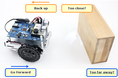
This example makes the ActivityBot try to keep a 32 cm distance between itself and an object in front of it. With no object detected, the robot will go forward until it finds one, then hone in and maintain that 32 cm distance. If you pull the object away from the ActivityBot, it will go forward to catch up. Likewise, if you push the object toward it, it will back up to restore that 32 cm distance.
The program declares five variables: distance, setPoint, errorVal, kp, and speed.
/*
  Follow with Ping.c

  Maintain a constant distance between ActivityBot and object.

*/

#include "simpletools.h"                      // Include simpletools header
#include "abdrive.h"                          // Include abdrive header
#include "ping.h"                             // Include ping header

int distance, setPoint, errorVal, kp, speed;  // Navigation variables

int main()                                    // main function
{
  setPoint = 32;                              // Desired cm distance
  kp = -10;                                   // Proportional control

  drive_setRampStep(6);                       // 7 ticks/sec / 20 ms

  while(1)                                    // main loop
  {
    distance = ping_cm(8);                    // Measure distance
    errorVal = setPoint - distance;           // Calculate error
    speed = kp * errorVal;                    // Calculate correction speed

    if(speed > 128) speed = 128;              // Limit top speed
    if(speed < -128) speed = -128;

    drive_rampStep(speed, speed);             // Use result for following
  }
}
The program starts off by making the setPoint 32 cm and the proportionality constant kp -10. It also sets the ramp step size to 6, which will cushion sudden changes in speed. Inside the while(1) loop the program makes the ActivityBot maintain a distance between itself and the target object by repeating five steps very rapidly:
An automated system that maintains a desired physical output level is called a control system. In the case of our ActivityBot, the level it maintains is the distance between itself and the object in front of it. Many control systems use a feedback loop to maintain the level, and our ActivityBot is a prime example of this. The measured distance is fed back into the system and compared against the set point for calculating the next speed, and this happens over and over again in a process called a control loop.
Engineers use drawings like this one to think through a control loop’s design and also to convey how it works to technicians and other engineers. If the set point (distance the ActivityBot tries to maintain) is 32 and the measured distance is 38, there is an error value. This error value is the set point – measured distance. That’s 32 – 38 = -6. This error is multiplied by a proportionality constant (kp) for an output that’s the speed to correct the error this time through the loop. That’s speed = kp x error value, or 60 = -10 x -6.
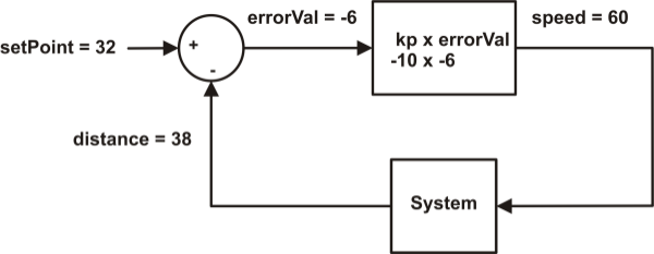
The circle is called a summing junction (for addition or subtraction), and the rectangular blocks designate operations that can vary. In this example, the top one is a proportional control block that multiplies error by a proportionality constant. The System block represents things we do not necessarily have control over, like if you move the object toward or away from the ActivityBot. Other common control blocks that were not used in this example are Integral, which allows corrections to build up over loop repetitions, and Derivative, which responds to sudden system changes.
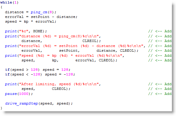
It’s really helpful to see how the values respond to different measured distances. To do this, all you have to do is add some print values to the screen.
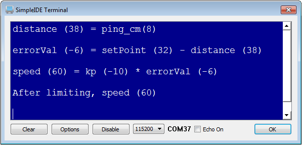
WARNING: This modified program is just for display, not navigation. For navigation, re-open Following with Ping.
If the measured distance is 40, errorVal = setPoint – distance results in errorVal = 32 – 40 = -8. Then, speed = kp * error is speed = -10 * -8 = + 80. So, the ActivityBot will try 80 ticks per second forward. This falls in the +/- 128 range, so the ActivityBot goes a little over half speed forward to catch up with the object. Now, try this for a distance of 24. The correct answer is speed = -80 which will make the ActivityBot back up. If the distance is 28 instead, the ActivityBot will back up less quickly, with a speed of -49.
There are lots of values to experiment with here. For example, if you change the setPoint variable from 32 to 20, the ActivityBot will try to maintain a distance of 20 cm between itself and an object in front of it. The value of kp can be increased to make it try to go faster to correct with smaller error distances, or slower to correct over larger error distances.
If you decrease the drive_setRampStep value, it will cushion the changes, but could cause it to respond so slowly that it runs into the object. If you increase it, it will respond more abruptly. Too large, and it could actually change direction so fast that it could even eject the Ping))) sensor from the breadboard!
Light sensors are used in all kinds of robotics, industrial, and commercial applications. Next, let's teach it to navigate by visible light. By using a pair of small light sensors, called phototransistors, your ActivityBot can measure and compare the light levels on its right and its left. Then, it can turn toward the brighter side as it navigates. This way, the ActivityBot can be programmed to follow a flashlight, or find its way out of a dark room to a bright doorway.
The Propeller C Simple Circuits tutorial has a page devoted to the same phototransistor that is included in your ActivityBot kit.
Welcome back!
Now, it's time to build and test two phototransistor circuits to give your ActivityBot phototransistor "eyes." Leave the piezo speaker circuit in place.
Build the circuit shown below.
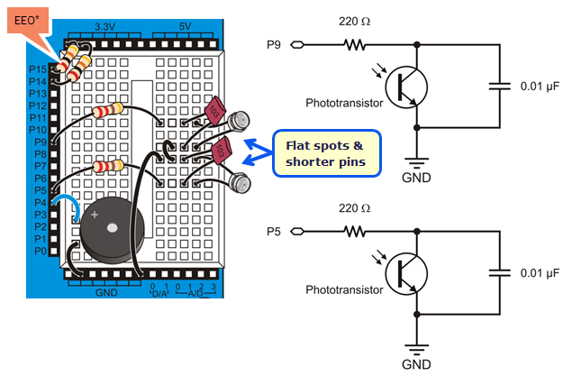
*P14/P15 resistors are only needed for ActivityBot kits using External Encoders (#32500).
This test will display raw light sensor readings in the SimpleIDE Terminal. You will need a flashlight or lamp that is brighter than the overall light level in the room.
The phototransistor circuits are designed to work well indoors, with fluorescent or incandescent lighting. Make sure to avoid direct sunlight and direct halogen lights; they would flood the phototransistors with too much infrared light.
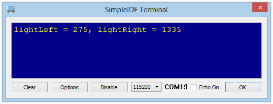
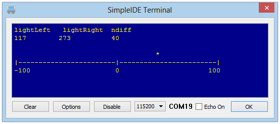
The values shown above were taken in a room with overhead fluorescent lighting. Notice how the lightRight measurement is larger - this was caused by cupping a hand over the right phototransistor.
Mismatched Measurements
It is unlikely that your two phototransistor measurements will match exactly. Each individual sensor will vary slightly as a natural part of the manufacturing process, and the brightness levels are rarely precisely even in any environment However, if one gives a measurement about 100 times larger than the other when exposed to the same level of light, that phototransistor is probably in backwards. Check your circuit and try again.
This simple program starts by declaring two int variables, lightLeft and lightRight, to hold values returned by the left and right phototransistor circuits.
The action happens inside a while(1) loop, which takes two light sensor measurements and displays the results over and over again.
Recall from the Sense Light tutorial [42] that phototransistor measurement is a two-step process. First, high(9) connects the phototransistor circuit to 3.3 V, allowing the capacitor in the circuit to charge up like a tiny battery. It only takes a moment to do that; pause(1) allows enough time. Immediately after charging the circuit, the next line of code calls the rc_time function to take a measurement at I/O pin 9 and store the result in lightLeft. The same steps are taken to store a sensor measurement in lightRight.
After that, the print statement prints the name of each variable followed by its value in decimal. The control character HOME returns the cursor to the upper left corner of the SimpleIDE terminal each time, and CLREOL clears out any characters left over from the previous measurement.
/*
  Test Light Sensors.c
*/

#include "simpletools.h"

int lightLeft, lightRight;

int main()
{
  while(1)
  {
    high(9);
    pause(1);
    lightLeft = rc_time(9, 1);

    high(5);
    pause(1);
    lightRight = rc_time(5, 1);

    print("%clightLeft = %d, lightRight = %d%c",
           HOME, lightLeft, lightRight, CLREOL);
    pause(250);
  }
}
Light travels in waves so small that the distance between adjacent peaks is measured in nanometers (nm), which are billionths of meters. The figure below shows the wavelengths for colors of light we are familiar with, along with some the human eye cannot detect, such as ultraviolet and infrared. The phototransistor in your ActivityBot kit detects visible light, but is most sensitive to 850 nm wavelengths, which is in the infrared range.
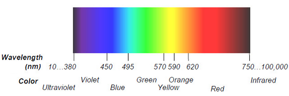
Just for fun, let's see if the phototransistor can detect different colors.
From your observation, do you think a clear phototransistor alone, like this one, could be used as a color sensor? Why or why not?
For ActivityBot navigation, the raw sensor values don't matter directly. What matters is the difference between the light levels detected by each sensor, so the the ActivityBot can turn to the side of the one sensing brighter light. It is also nice to have values that will fall into a predictable range that can integrate easily with code to drive the servo motors.
Accomplishing this is surprisingly simple. First, just divide one sensor measurement into the sum of both. The result will always be in the 0 to 1 range. This technique is an example of a normalized differential measurement. Here’s what it looks like as an equation:
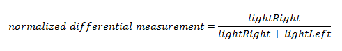
Two more simple operations will make the result easier to use. First, multiplying the result by 200 will make the result a whole number. Second, subtracting 100 from that whole number will always return values from -100 to 100. If the phototransistors sense the same level of light, regardless of how bright or dim, the final whole number will be zero. This is an example of a zero-justfied normalized differential measurement, let's call it "ndiff" for short. Now our equation looks like this:
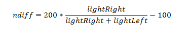
The example code below will display the lightRight and lightLeft measurements, and also show the value of ndiff as an asterisk over a number line. This makes it easier to visualize how the ActivityBot navigation program uses the sensor values to aim for a new trajectory towards the brighter light.
Display Troubles?
If you have resized your SimpleIDE Terminal window smaller than this example program needs it to be, you will likely get garbled results. Just resize the terminal wider and then click Run with Terminal again.
It's a long read, but an interesting one if you want to understand how the graphical display was generated using print statements with the simpletools library.
This program builds on Test Light Sensors. Two more variables are declared in addition to lightLeft and lightRight; ndiff holds the result of the fancy-named equation, and position will be used to place the asterisk in the SimpleIDE terminal.
Inside main, a set of three print statements define the display layout for the SimpleIDE Terminal.
The first print displays the value of the variables listed, and the \n (new line) formatters make three blank lines to make room for the asterisk that will display over the number line.
The second print displays the number line, followed by a \n formatter.
The third print displays the labels for the number line, followed by a \n formatter.
Then, a char array named s is declared and initialized with 51 space characters, which will be used to position the asterisk over the number line.
Next, the code enters a while(1) loop. The next 8 lines, which obtain the raw phototransistor measurements, should be familiar by now.
The next line beginning with ndiff is the same as the ndiff equation shown above.
The three print statements below the ndiff expression (1) position the cursor, (2) display the updated decimal values of lightRight, lightLeft, and ndiff, and clear out any characters left from last time, and (3) move the cursor to the line the asterisk will use.
Next, position = (ndiff + 100) / 4; offsets ndiff with +100 to ensure it is a positive number, and then scales it with /4 to fit the scale of the number line. The result is a number that is useful for positioning an asterisk in the SimpleIDE Terminal, and it is assigned to the position variable.
This is how the asterisk gets placed: s[position] = '*'; redefines the "position-th" element in the s array to be an asterisk instead of a space. Then, the asterisk is displayed in the proper position with print(s); which displays all of the elements in the s array - a series of spaces with just one asterisk.
Immediately, s[position] = ' '; redefines the "position-th" element to be an empty space again, so the asterisk can be re-positioned on the next run through the loop. Without this line, the display would start accumulating asterisks.
The loop finishes up with pause(350); before repeating. If you read this far, thank you for your perseverance!
/*
  Test Light Sensors Graphical.c
*/

#include "simpletools.h"


int lightLeft, lightRight, ndiff, position;

int main()
{
  print("lightLeft   lightRight  ndiff\n\n\n\n");
  print("|------------------------|------------------------|\n");
  print("-100                     0                      100\n");
  char s[51] = {"                                                   "};

  while(1)
  {
    high(9);
    pause(1);
    lightLeft = rc_time(9, 1);

    high(5);
    pause(1);
    lightRight = rc_time(5, 1);

    ndiff = 200 * lightRight / (lightRight + lightLeft) - 100;

    print("%c%c", HOME, CRSRDN);
    print("%d        %d          %d", lightLeft, lightRight, ndiff);
    print("%c%c%c", CLREOL, CRSRDN, CR);

    position = (ndiff + 100) / 4;
    s[position] = '*';
    print(s);
    s[position] = ' ';

    pause(350);
  }
}
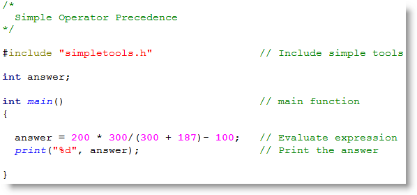
Parentheses Matter. In C language mathematical expressions, like the one in this example program, multiplication and division operations are performed before addition and subtraction. However, surrounding an operation with parentheses causes it to be evaluated first, working from innermost operation on out in the case of nested parentheses. These rules are part of a larger ruleset called operator precedence; each programming language has its own operator precedence ruleset.
To see what difference a set of parentheses makes, create this small project that uses the same mathematical expression as the program above.
Are you convinced that parentheses make a difference yet?
Now, let's make the ActivityBot follow light! The following code should allow your robot to follow a flashlight beam, or navigate out of a dark room through a brightly lit doorway.
This program uses the simpletools and abdrive libraries. After initializing some variables, the program consists of an infinite loop which receives values from the phototransistors and uses them to adjust the servos' speeds to navigate toward whichever side detects brighter light.
First, the now-familiar int variables lightLeft, lightRight, and ndiff are declared for taking and using the sensor measurements. Then, int variables speedLeft and speedRight are declared for use with the drive_speed function later on.
The first six lines in the main function's while(1) loop are straight out the test programs; they take the light sensor measurements and store the values in lightLeft and lightRight.
The next line is the same ndiff equation used in Test Light Sensor Graphical. It divides lightRight by lightRight + lightLeft. The result is multiplied by 200, and then 100 is subtracted from it. This yields a value in the range of -100 and 100, which is assigned to ndiff. Positive ndiff values mean the left photoresistor is sensing brighter light, and negative ndiff values mean the right photoresistor is sensing brighter light. The farther the value is from zero, the greater the difference between what the two phototransistors are sensing.
The variables speedLeft and speedRight are then initialized to 100; keep this in mind when looking at the if code block that comes next.
The first condition translates to "if ndiff is greater than or equal to zero (brighter light on the the left), make speedLeft equal to 100 minus ndiff*4." The new value for speedLeft would be something less than 100, while speedRight remains 100, when those variables are used in the drive_speed function call right below the if block. For example, if ndiff = 50, this statement is the same as speedLeft = 100 - (50*4), which equals -100. The result is drive_speed(-100, 100) which makes the ActivityBot rotate to the left toward the light.
However, if ndiff is NOT positive, the code drops to else speedRight += (ndiff * 4). This translates to "make speedRight equal to 100 plus ndiff*4." This still yields a number smaller than 100; remember that ndiff is negative here. For example, if ndiff = -25, this statement is the same as speedRight = 100 + (-25*4) so speedRight ends up equal to zero, while speedLeft is still 100. This giving us drive_speed(100, 0), causing the ActivityBot to pivot right towards the brighter light.
/*
  Navigate by Light.c
*/

#include "simpletools.h"
#include "abdrive.h"

int lightLeft, lightRight, ndiff;
int speedLeft, speedRight;

int main()
{
  while(1)
  {
    high(9);
    pause(1);
    lightLeft = rc_time(9, 1);

    high(5);
    pause(1);
    lightRight = rc_time(5, 1);

    ndiff = 200 * lightRight / (lightRight + lightLeft) - 100;

    speedLeft = 100;
    speedRight = 100;
    if(ndiff >= 0) speedLeft -= (ndiff * 4);
    else speedRight += (ndiff * 4);

    drive_speed(speedLeft, speedRight);
  }
}
Phototaxis — This is the term that describes an organism moving its whole body in direct response to light stimulus. Moving towards brighter light is called positive phototaxis, and moving away from brighter light would then be negative phototaxis. While the Navigate by Light program makes the ActivityBot mimic positive phototaxis, in nature, it seems this behavior is usually found in microscopic organisms. Moths are attracted to light, but their varied and circling flight paths around a streetlamp demonstrate that their navigation systems are far more complex.
Would you like to make your ActivityBot mimic negative phototaxis? It can be done by replacing one single variable in the Navigate by Light code.
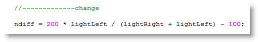
Many TVs and other equipment are controlled by infrared remotes. When you point the remote at the TV and press the channel-up button, it changes the channel for you. Pressing the button makes the remote flash a pattern of infrared light at the TV. Infrared light is not visible to humans, but the TV’s infrared receiver detects the flashing light pattern. The TV’s microcontroller decodes this pattern and uses that information to change the channel for you.
The infrared light (IR LED) and receiver work great as "flashlights" and "eyes" for your ActivityBot. The IR LEDs shine forward, and the IR receivers detect reflections off of nearby obstacles.
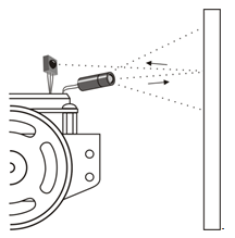
The Propeller microcontroller receives reflection data from the IR receivers and uses it to make navigation decisions. In this way, your ActivityBot can roam around obstacles without first bumping into them.
In this activity, you will build and test the infrared object sensors to make sure they detect objects in front of the ActivityBot.
(2) IR LEDs
(2) IR receivers
(2) 1 k-ohm resistors (brown-black-red)
(2) 220-ohm resistors (red-red-brown)
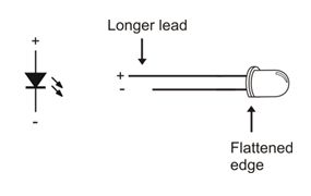
To direct the IR LED’s light, just like a flashlight beam, we’ll use an IR LED standoff (longer tube) and shield (shorter tube).
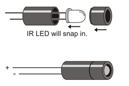
Although the shield friction-fits into the standoff, it can be helpful to place a small piece of clear tape around the tube where they meet to hold them together securely. Make sure the tape does not extend beyond the end of the tube or cover the IR LED.
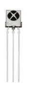
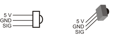
The IR LED’s cathodes are connected to D/A0 and D/A1. For object detection, the D/A outputs are set to 0 V = GND. Their voltage can be increased to make the IR LEDs dimmer, for closer range detection. (They can even be tested at different voltages—levels of dimness—to get a rough idea of the object’s distance, but that's for another activity...)
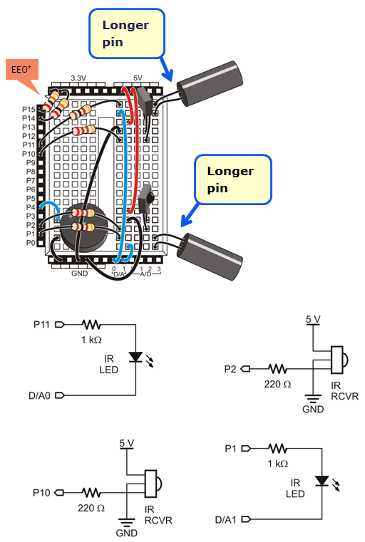
*P14/P15 resistors are only needed for ActivityBot kits using External Encoders (#32500).
The test code displays the state of each IR detector: 1 = no infrared reflection detected, 0 = yes, infrared reflected from an object is detected. Before continuing, make sure that both sides can reliably detect objects.
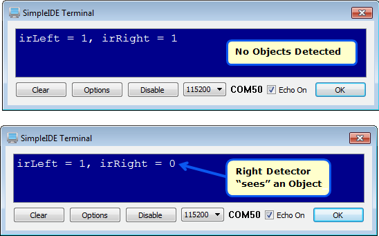
It's important to make sure both IR detectors work properly before continuing.
What the IR Sensors Can't See
Remember, the IR sensor system is looking for reflected infrared light. Light-colored objects reflect infrared light well, while dark-colored objects absorb infrared light instead of reflecting it. So, if your IR sensors can't see your black shoes, or a black plastic wastebasket, don't worry, that is normal!
First, int variables irLeft and irRight are declared to hold the IR detector output states. Then, inside main, the code sets P26 and P27 low to make sure that the D/A terminals are both providing 0 V to the IR LED cathodes.
The IR receivers are designed to only send detect signals if they see infrared light that flashes on/off at 38,000 times per second (38 kHz). So, in the main function’s while loop, freqout(11, 1, 38000) sends sends high/low signals that repeat 38000 times per second to the IR LED’s anode. This makes it flash on/off at that rate.
Next, irLeft = input(10) saves the IR receiver’s output in the irLeft variable. If the IR receiver’s output is high, meaning no IR reflection detected, input(10) returns a 1. If the receiver’s output is low, meaning reflected IR was detected, intput(10) returns a 0. The same process repeats for the right IR detector with freqout(1, 1, 38000) and irRight = input(2).
/*
  Test IR Detectors.c
*/

#include "simpletools.h"                        // Include simpletools

int irLeft, irRight;                            // Global variables

int main()                                      // main function
{
  low(26);                                      // D/A0 & D/A1 to 0 V
  low(27);

  while(1)                                      // Main loop
  {
    freqout(11, 1, 38000);                      // Left IR LED light
    irLeft = input(10);                         // Check left IR detector

    freqout(1, 1, 38000);                       // Repeat for right detector
    irRight = input(2);

    print("%c irLeft = %d, irRight = %d",       // Display detector states
           HOME,       irLeft,       irRight);
    pause(100);                                 // Pause before repeating
  }
}
After the two infrared detection results are stored in irLeft and irRight, print(%c irLeft = %d, irRight = %d”, HOME, irLeft, irRight) does several things. The %c makes it send the HOME value (1) to SimpleIDE Terminal. That sends the cursor to the top-left position. After that, irLeft = %d, irRight = %d displays irLeft = followed by the 1 or 0 that irLeft stores, then irRight = followed by the 1 or 0 that irRight stores. Last, pause(100) keeps the rate that the SimpleIDE Terminal is updated down in the 10 times per second neighborhood.
Infrared — It means “below red”, and it refers to the fact that the light’s frequency is below that of red on the color spectrum.
Filtering — The IR receiver has a filter built in that makes it look for infrared that flashes on/off 38000 times per second (38 kHz). This allows it to differentiate between infrared coming from the TV remote and other IR sources such as halogen and incandescent lamps as well as sunlight streaming in through a nearby window.
Sunlight — Even though the IR receiver filters for sunlight, direct sunlight can often swamp the IR LED’s signal. Try to keep it indoors and out of any sunlight streaming in through windows.
The P26 and P27 lines are currently in use providing 0 V to the IR LED cathodes, so we cannot use their LEDs for indicating the IR detector states like we did with whiskers. So, let’s build some LEDs on the breadboard for indicators.
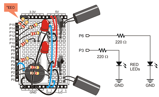
*P14/P15 resistors are only needed for ActivityBot kits using External Encoders (#32500).
Next, modify the code to turn a given light on if its IR receiver returns 0, or off if it returns 1.
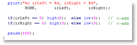
You can further modify your IR detection code from Try This so that it sounds an alarm if it detects IR interference from the environment. This is a useful test to find out if nearby fluorescent lights are sending out signals that are interfering with your detector. The key is to not emit any infrared with the IR LEDs. If the receivers still send a low signal, there must be IR interference coming from another source. If interference is detected, make the piezospeaker get your attention with a series of six 50 ms, 4 kHz chirps separated by six 50 ms pauses. You can use a TV remote to test this.
With your IR object sensors built and tested, you are ready to make your ActivityBot roam and avoid obstacles without bumping into them.
The IR Roaming code example makes the ActivityBot go forward until it detects an obstacle. If it sees an obstacle on the left, it’ll turn right. Likewise, if it sees one on the right, it’ll turn left, and if it sees obstacles on both left and right, it’ll back up.
Not all obstacles are visible.
Many black objects will absorb infrared light instead of reflecting it. If in doubt, use your LED indicator program from the Build and Test the IR Detectors "Try This" section. The LEDs will show you if the object is visible to the IR object detectors.
This example is almost identical to Test IR Detectors.c from Build and Test the IR Sensor Circuits. The code changes are:
/*
  IR Roaming.c

  Use IR LEDs and IR receivers to detect obstacles while roaming.

*/

#include "simpletools.h"                        // Library includes
#include "abdrive.h"

int irLeft, irRight;                            // IR variables

int main()                                      // main function
{
  low(26);                                      // D/A0 & D/A1 to 0 V
  low(27);

  drive_setRampStep(12);                        // Max step 12 ticks/s every 20 ms

  while(1)
  {
    freqout(11, 1, 38000);                      // Check left & right objects
    irLeft = input(10);

    freqout(1, 1, 38000);
    irRight = input(2);

    if(irRight == 1 && irLeft == 1)             // No obstacles?
      drive_rampStep(128, 128);                 // ...full speed ahead
    else if(irLeft == 0 && irRight == 0)        // Left & right obstacles?
      drive_rampStep(-128, -128);               // ...full speed reverse
    else if(irRight == 0)                       // Just right obstacle?
      drive_rampStep(-128, 128);                // ...rotate left
    else if(irLeft == 0)                        // Just left obstacle?
      drive_rampStep(128, -128);                // ...rotate right
  }
}
The drive_rampStep function is designed to be used in loops. After our call to drive_setRampStep(12), if a loop calls drive_rampStep(128, 128) it will increase speed 12 ticks/second at a time toward a final 128 ticks per second every time it’s called. If it’s calling 50 times per second (20 ms pauses), it will take 11 repeated calls (11/50ths of a second) to get to full speed. After the ActivityBot reaches full speed, repeated calls to drive_rampStep(128, 128) don’t change the speed any because it’s already there. If the loop then starts repeating drive_rampStep(-128, -128) calls, it’ll take 22/50ths of a second (getting close to half a second) to ramp from full speed forward to full speed reverse.
The if…else if…else if…else statement is what uses the irLeft and irRight detection result values for navigation. For example, if(irRight == 1 && irLeft == 1) it means that no objects are detected, so drive_rampStep(128, 128) sends the ActivityBot a 12 ticks/second step toward 128 ticks per second if it both wheels aren’t already running at that speed. If the ActivityBot sees an obstacle on it’s right, the else if(irRight == 0) condition becomes true, so each time through the loop, it takes 12 ticks/second steps toward rotating left in place every 50th of a second. Rotating in in place is achieved with the left wheel turning at full speed backwards at -128 ticks/second and the right turning at 128 ticks/second forward.
As the ActivityBot rotates left to avoid the right obstacle, the obstacle will disappear from the right detector’s view. At that point, the detection states will go back to irLeft == 1 and irRight == 1, which will make the first if statement true again, and drive_rampStep(128, 128) will start ramping back to full speed forward.
A pause between while(1) loop repetitions is not needed because the drive_rampStep function delays 1/50th of a second before returning.
drive_setRampStep — This function sets the maximum change in speed that drive_rampStep can cause every 1/50 of a second. The abdrive library defaults to 4, which means that the largest change in speed allowed is 4 ticks/second every 50th of a second. Although that default makes drive_ramp and drive_rampStep maneuvers nice and smooth, it’s not enough change in a small amount of time to detect and avoid obstacles at full speed. So, drive_setRampStep(12) triples the speed change allowed every 50th of a second. Not quite as smooth, but responsive enough to avoid the obstacles.
You can reduce the roaming speeds by changing the 128's in the program to lower values.
Increasing the value used in the drive_setRampStep function call to a higher value will make the robot more responsive, but also more twitchy. Reducing the value will make it smoother, but at some point, it won’t respond quickly enough and it will run into obstacles.
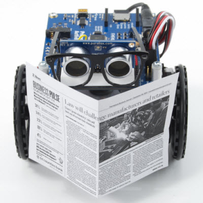
The "Extras" section includes optional activities/tutorials and troubleshooting tips for your ActivityBot, or the Propeller Activity Board (original or WX version). Sort of like an appendix.
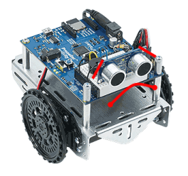
This page lists some of the most common problems encountered when calibrating the ActivityBot, or programming it to drive for the first time.
If you don't find your specific problem here, or need more help, contact Parallax Technical Support by email (support@parallax.com [44]), or by phone 916 -624-8333 (toll-free: 888 99-STAMP within USA only). You can also post a question in the Learn Forum [45] to get help from the community.
Solution: First, if the servos do not turn at all, make sure the power switch is in Position 2 (which powers the servo headers), and not Position 1. If that doesn't help, check the batteries. Low batteries or batteries that are placed in backward will not provide enough power to the ActivityBot to run all of its components effectively. This can result in slower speeds, resets, or loss of functionality.
Solution: First, if the servos do not turn at all, make sure the power switch is in Position 2 (which powers the servo headers), and not Position 1. If that doesn't help, check the servo port jumper positions. The jumper for P12 and P13 should be set to VIN — if it is set to 5V the servos will not receive enough power. Follow the Electrical Connections [46] page instructions for moving the jumper, and then run the calibration again.
DO NOT MOVE THE JUMPER WHILE POWER PLUG OR USB CABLE IS CONNECTED TO THE BOARD.
Solution: Potentially, a short-circuit has damaged your Activity Board (original or WX version). Position 1 on the 3-position switch should not power the 3-pin headers above the breadboard that the servos and encoders are plugged into. This problem can often be caused if the shunt jumper for P12 & P13 was moved while the Activity Board (original or WX version) was receiving power from the USB port or barrel jack. Unfortunately, there is no solution for this problem once it has occurred, please contact technical support (see contact information at the top of this page).
Solution: Check the USB connection on the Activity Board (original or WX version). The USB connection port on the ActivityBot is designed to fit tightly to the Mini B connector. Even though it may feel secure, sometimes the cable may not be inserted fully into the port, and this will cause your computer not to recognize the connection or give an error.
Solution: Check your servo cables. A common mistake is to accidently switch the cables for left and right servos, which causes the ActivityBot to go backwards when it should go forward, left when it should go right, etc. Check to make sure the left and right connections match the Electrical Connections [46] page instructions, and then run the calibration again.
Solution: The right and left encoder cables may be swapped. This prevents the ActivityBot from correctly calibrating or using information from the encoders. A way to check if this is the problem is to look at the calibration table or try the test program here [47]. A successful calibration table shows columns of ascending and descending values, like the one on the Calibrate Your ActivityBot [48] page. If the encoder cables are swapped, there will be long sequences of identical numbers instead, like in the image below. Reconnect the encoder cables following the Electrical Connections [46] page instructions, and then run the calibration again.
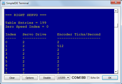
Solution: Check that you don't have a servo and encoder cable swapped (to quickly test this, try the test program here [47]). If so, your Interpolation table will look similar to the one below (the image is for a left servo for left encoder switch). If the left wheel doesn't turn, your left servo and encoder cables might be switched. If the right wheel doesn't turn, your right servo and encoder cables might be switched. If no wheel turns, you might have both right and left swapped. Recheck your connections using the Electrical Connections [46] page and try the calibration again.
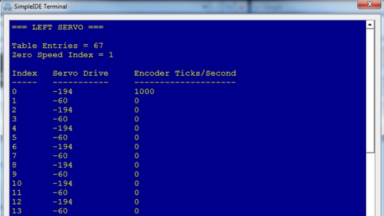
Solution: You may need to adjust the servo or servo bracket. Check the position of the servo inside its hole in the chassis.
Notice that there is a little bit of space around the servo. If the servo is tight against the top edge of the hole close to the encoder, with a gap left below the servo, the beam of infrared light coming from the encoder sensor might be missing the wheel spokes and hitting the solid ring below them instead.
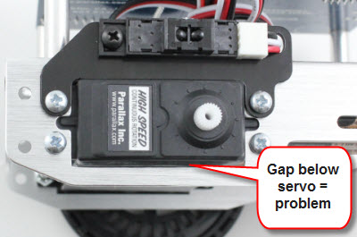
To fix this, loosen the servo's locknuts and then reposition the servo so the gap is between the servo and the encoder. This should ensure that the encoder sees only spokes and holes. Make sure that the servo doesn't shift position when you retighten the locknuts.
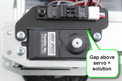
(Note: the encoder bracket was redesigned in October 2013 to mitigate this issue.)
Solution: The encoder IR sensor may not be functioning correctly. Check the encoder cable plug on both ends to make sure it is seated properly. Re-run the calibration a second time and check the interpolation table again using the Display Calibration program. If there is no change, please get in touch with Technical Support using the contact information above. There is no fix for a malfunctioning encoder; it may need to be replaced.
Solution: First, check to make sure the resistors connecting P14 and P15 to 3.3 V are marked red-black-orange (20 k-ohm). Next, check to make sure your encoder cables are not plugged into the 3-pin headers upside down. White wire should be near the top edge of the board, black wire should be near the 5V labels.
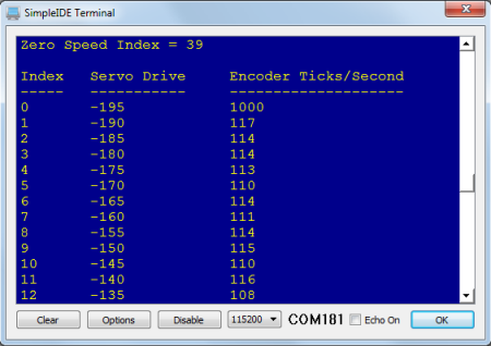
Solution: Check your jumper settings for the servos. They should be set to VIN, not 5V. If they are set to 5V, disconnect all power (barrel jack AND USB must be unplugged, power switch set to 0) to the board and move the jumper to VIN as shown on the Electrical Connections [46] page. Once this is completed, re-run the calibration.
Solution: Your servos may be manually uncentered beyond what the calibration program can compensate for. Try running the following code (by opening a new project), and using a small screwdriver to very gently turn the potentiometer in the small hole in the back of your affected servo until the wheel stops spinning. You must re-run the calibration program once you perform manual calibration – do not forget to do this!
/*
ActivityBot Servo Centering.c
*/
#include "simpletools.h"                      // Include simpletools
#include "servo.h"

int main()                                    // Main function
{
  servo_set(12, 1500);
  servo_set(13, 1500);
}

Links
[1] https://learn.parallax.com/tutorials/robot/activitybot/propeller-c-programming-activitybot-360%C2%B0
[2] http://www.parallax.com/product/32600
[3] http://www.parallax.com/product/32500
[4] http://learn.parallax.com/tutorials/language/propeller-c/propeller-brains-your-inventions
[5] http://learn.parallax.com/tutorials/language/propeller-c/propeller-c-set-simpleide
[6] http://learn.parallax.com/tutorials/language/propeller-c/propeller-c-start-simple
[7] http://learn.parallax.com/tutorials/language/propeller-c/propeller-c-functions
[8] mailto:support@parallax.com?subject=ActivityBot%20help%20needed
[9] http://learn.parallax.com/node/689
[10] http://www.parallax.com
[11] http://learn.parallax.com/node/741
[12] http://learn.parallax.com/node/745
[13] http://learn.parallax.com/node/746
[14] http://learn.parallax.com/node/748
[15] https://www.parallax.com/sales/contact-sales/
[16] https://learn.parallax.com/propeller-c-set-simpleide
[17] https://learn.parallax.com/propeller-c-start-simple
[18] https://www.parallax.com/downloads/propeller-c-learn-folder
[19] https://www.parallax.com/downloads/propeller-activity-board-wx-product-guide
[20] https://www.parallax.com/downloads/propeller-activity-board-guide
[21] https://learn.parallax.com/reference/breadboard-basics
[22] https://learn.parallax.com/propeller-c-simple-circuits/blink-light
[23] https://learn.parallax.com/propeller-c-simple-circuits/piezo-beep
[24] https://learn.parallax.com/activitybot/software-and-programming
[25] https://learn.parallax.com/propeller-c-set-simpleide/update-your-learn-folder
[26] http://learn.parallax.com/node/880
[27] http://learn.parallax.com/node/1715
[28] http://learn.parallax.com/729
[29] http://learn.parallax.com/tutorials/robot/activitybot/blocklyprop-robotics-activitybot/electrical-connections
[30] https://www.parallax.com/downloads/parallax-feedback-360%C2%B0-high-speed-servo-product-guide
[31] http://learn.parallax.com/node/731
[32] http://learn.parallax.com/node/1714
[33] https://learn.parallax.com/activitybot/troubleshooting#encoder
[34] http://learn.parallax.com/node/729
[35] https://learn.parallax.com/activitybot/electrical-connections
[36] https://learn.parallax.com/activitybot/troubleshooting
[37] http://learn.parallax.com/activitybot/software-and-programming
[38] http://learn.parallax.com/propeller-c-set-simpleide/update-your-learn-folder
[39] https://learn.parallax.com/propeller-c-start-simple/counting-loops
[40] https://learn.parallax.com/reference/speed-sound-air-vs-temperature
[41] https://learn.parallax.com/support/reference/speed-sound-air-vs-temperature
[42] https://learn.parallax.com/propeller-c-simple-circuits/sense-light
[43] https://learn.parallax.com/activitybot/beeps
[44] mailto:support@parallax.com
[45] http://forums.parallax.com/forumdisplay.php/49-Learn
[46] https://learn.parallax.com/activitybot/electrical-connections#AB-Check-Connections
[47] https://learn.parallax.com/activitybot/test-encoder-connections
[48] https://learn.parallax.com/activitybot/calibrate-your-activitybot