Search
How the Supply Rail Tests Work
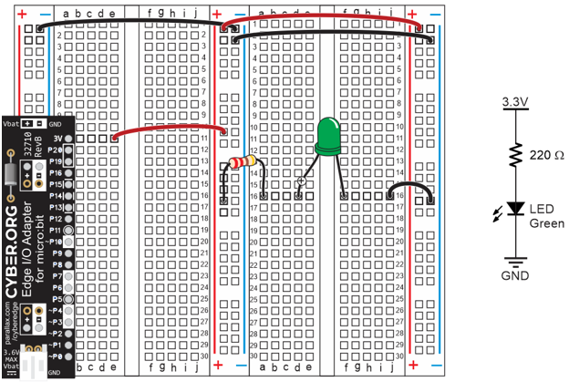
The wires you added to the breadboard it easy to connect circuits you build on the terminal stips to supply voltages on the bus strips.
The two levels of supply voltage in your prototyping system are 3 V and 0 V.
You can connect a circuit to 3 V by plugging a wire or lead into one of the center and right bus strips’ plus (+) sockets. Those are the ones next to the red lines, and also shaded red in the animation.
Activity 2: Field-Test the Whiskers
What if you have to test the whiskers at some later time away from a computer? In that case, the Serial Monitor won’t be available, so what can you do? One solution would be to use LED circuits to display the whisker states. All it takes is a simple sketch that turns an LED on when a whisker is pressed or off when it’s not pressed.
Parts List:
(2) resistors, 220 Ω (red-red-brown)
(2) LEDs, red
Test the IR Receiver and Remote
IR Receiver Circuit
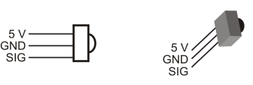
If you have not used the IR Receivers with your ActivityBot before, take a look at the pictures below. The infrared receiver needs three connections: 5 V, GND, and an I/O pin to read the signal it sends. The circuitry inside the infrared receiver makes it safe to connect its signal pin to the Propeller I/O pin with a small resistor, even though the sensor is powered by 5 V.
Breadboard Setup and Testing for micro:bit
What it’s about
In these activities, you will set up and test your breadboard prototyping system for your micro:bit module. Along the way, you will learn some important circuit building and measuring skills.
Before you start
You will need:
Connect and Test the Arlo + BOE Ping))) Sensors
Connect and Test the Arlo + BOE Ping))) Distance Sensors
Connect & Test Activity Board Arlo Ping))) Sensors
This connection diagram (below) shows where to connect each 3-wire Ping))) sensor cable. If you’re looking at the color version, note that each black wire is connected to either GND on the breadboard, or the GND terminal in the servo header. Each of those black wires should also be connected to a Ping))) sensor’s GND pin. The power selection jumper between the P13 and P14 servo ports should also be set to 5V, likewise for the one between P15 and P16.
Connect & Test BOE Shield + Arlo Ping))) Sensors
Connect and Test the Ping))) Distance Sensors
The diagram below shows where to connect each 3-wire Ping))) sensor cable. If you’re looking at the color version, note that each black wire is connected to either GND on the breadboard, or the GND terminal in the servo header (labeled Black to the right of the header block). Each of those black wires should also be connected to a Ping))) sensor’s GND pin.
Putting the Pieces Together
You will need to add the veho360 speaker and its mounting bracket, the whisker circuits, and one IR receiver circuit to your ActivityBot. You will also need to configure your IR remote for Sony protocol.
WAM Activites with Boe-Bot Parts
What's a Microcontroller? activites you can do with Boe-Bot Robot Parts
Question: "What activities can we do from the "What’s a Microcontroller?" text using the parts included in the Boe-Bot Robot Kit?”
Answer: "Quite a lot!"
Teachers frequently ask this question, so we have made a list below, for your reference. It shows the cross-compatibility for using the "What's a Microcontroller?" v3.0 with just the parts included in the Boe-Bot Robot kits v3.0.