Chapter 6 Challenges
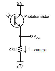
Phototransistor Voltage Output Circuit
Even though the Propeller chip can play WAV files and synthesize speech, sometimes a simple beep is all the noise you need to get the job done.
The first breadboard circuit we'll build for the ActivityBot is a simple piezo speaker.
It is very easy to make this speaker beep with a single line of code:
In this tutorial's activities, the pushbuttons you add will be used to control the lights from LED Lights. You will also use the alligator clip probes to test continuity between pushbutton terminals and voltages at key points in pushbutton circuits.
Robots have been in use for all kinds of manufacturing and in all manner of exploration vehicles—and in many science fiction films—for a long time. The word ‘robot’ first appeared in a Czechoslovakian satirical play, Rossum’s Universal Robots, by Karel Capek back in 1920! Robots in this play tended to be human-like, and much science fiction that followed involved these robots trying to fit into society and make sense out of human emotions.
![]()
This tutorial shows you how build an IR Beacon that your ActivityBot can seek, using BlocklyProp graphical programming.
The Propeller microcontroller has 32 input/output pins, or I/O pins, labeled P0 through P31. The Propeller can interact with other circuits connected to these I/O pins, through programs that use these labels. A Propeller I/O pin can do three things:
This chapter covered BOE Shield-Bot assembly and testing. Assembly involved both mechanical construction and circuit-building, and testing used some new programming concepts. Here are the highlights:
Hardware Setup
Electronics