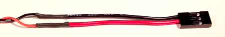
The the black and red power cable soldered to the Tarot T-2D Gimbal Control Circuit doesn't come with any connectors, so you'll have to add one that is compatible with the 0.1"-pitch male right-angle header on the ELEV-8 Power Distribution Board. There are a few different options to make the connection. If you have a pin crimping tool, option one should be easiest for you. If you don't have that specialty tool but do have soldering equipment, we recommend option 2.
Option 1 - Crimp Connector
For this method, you need one JR-type female "servo" connector housing and pins (such as Pololu #1924; JR Connector 3-Pack, Female) and a specialty tool for crimping the pin connectors (such as the IWISS SN-28B or Pololu #1928). If you have the right equipment, this is the easiest and fastest method, but option 2 will work just as well for those that don't.
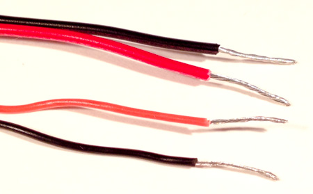
- Use the wire strippers to carefully remove about 1/8 inch (3 mm) of insulation from the end of each wire. Take each wire and twist it using your fingers to bring all of the individual wire strands together. If the ends are already stripped, then skip this instruction.
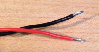
- Use your pin crimping tool to attach a female pin to the end of each wire. You may find this YouTube tutorial helpful.
- Before sliding the connectors into the housings, please check them against this inspection chart.
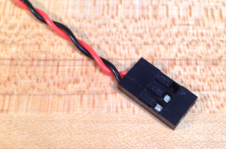
- Slide the red wire into the center slot of the connector housing and the black wire into one of the sides, until they click into place. (Your wire may look slightly different)
ption 2 - Splice (Solder) Servo Extension Cable
For this method, you'll need a soldering iron, solder, a 3-wire servo extension cable (such as any of the cables in Parallax #751-00010), 1" of some 1/16" or 1/8" diameter heat-shrink tubing, and a heat gun if you have one. By removing the old connector on the gimbal cable assembly and soldering on a cable that already has a 3-pin female servo connector on the end, you can avoid having to crimp your own connector, but still end up with a reliable connection.
- Use your wire strippers or scissors to cut off the red "JST" connector, just behind the connector (see image for Option 1, Step 1)
- Cut the 3-wire extension cable so that you have a 3" piece of wire with a connector on the end.
- Pull/cut off the white wire on the extension cable.
- Use the wire strippers to carefully remove about 1/4 inch (6 mm) of insulation from the end the red and black wires on the 3-pin extension cable and the gimbal cable assembly. Take each wire and twist it using your fingers to bring all of the individual wire strands together.
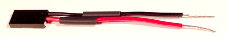
- Slide a 1/2" long piece of heat shrink tubing down onto both 3-pin extension wires.
- "Tin" all four wires. If you have not done this before, follow Instructions 2 through 4 of Step 2 from the ELEV-8 v2 Assembly Guide.
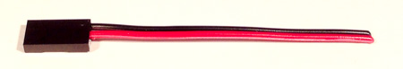
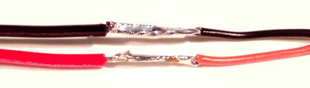
- Solder the wires together so that they exactly match the image below. If you don't have much soldering experience, we recommend practicing with some scrap wire first.
- Slide the heat-shrink tubing back over the connector so that there is not exposed metal wire or solder. Use a heat gun, hair dryer, or soldering iron to shrink the tubing. See instructions 3 through 5 of Step 7 of the ELEV-8 v2 Assembly Guide for more detail.