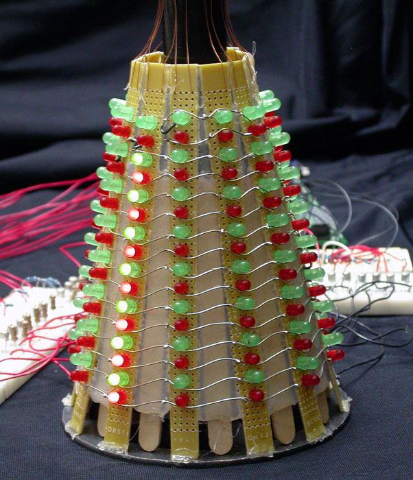
My project is a randomized bouncing light Christmas tree used to decorate for the Christmas season. This LED Christmas tree utilizes a 12 by 16 LED matrix mounted on a metal frame.
The programming is operated by a Basic Stamp 2 microcontroller. There are 2 sequences used for the display. In the first sequence, the supply side circuitry is controlled by 12 pins on the Basic Stamp. Each pin is attached to a 1k Ω resistor. Each resistor leads to its own PNP transistor. From there, each signal goes through a 150 Ω resistor.
The circuit continues to the supply side of the LED matrix, and the LEDs are mounted in 12 single vertical rows of 16 on electronic bread boards. These boards are placed on the metal frame in a Christmas tree shape. The ground side of the circuitry is controlled by the decoder multiplexer. These pins lead to three 74HC04 ICs which convert the signals from the 74HC154N Multiplexer. Then the signal from each pin goes through a 1k Ω resistor so the NPN transistors work properly. Then the NPN transistors are connected to the ground side of the matrix.
The display works by using a randomizer programmed on the Basic Stamp that creates a number which is divided by 12 and then that remainder is used as the output number. That number is then utilized through a case statement. The number determines the case and the case statement turns on a certain pin on the Basic Stamp. This activates the corresponding vertical row on the display.
The ground horizontal row is controlled by a binary counter that is set up to count from 0 to 15 and those numbers are sent to the input on the 74HC154N IC and multiplexed to the output pins from 1 to 16, and then the binary counter is changed from counting from 0 to 15 to 15 to 0 thereby reversing the order of the output pins on the 74HC154N IC. When a ground pin is activated, it can complete a circuit with a positive pin that has been activated, and an LED lights up. In the second sequence both the supply side and ground side have a randomizer function to make the LEDs light in a completely random order. The speed at which the LED’s turn on is controlled by the DelayTm constant programmed into the Basic Stamp.